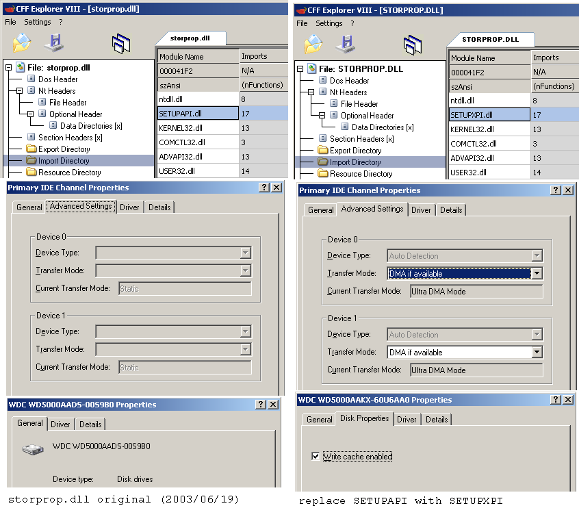
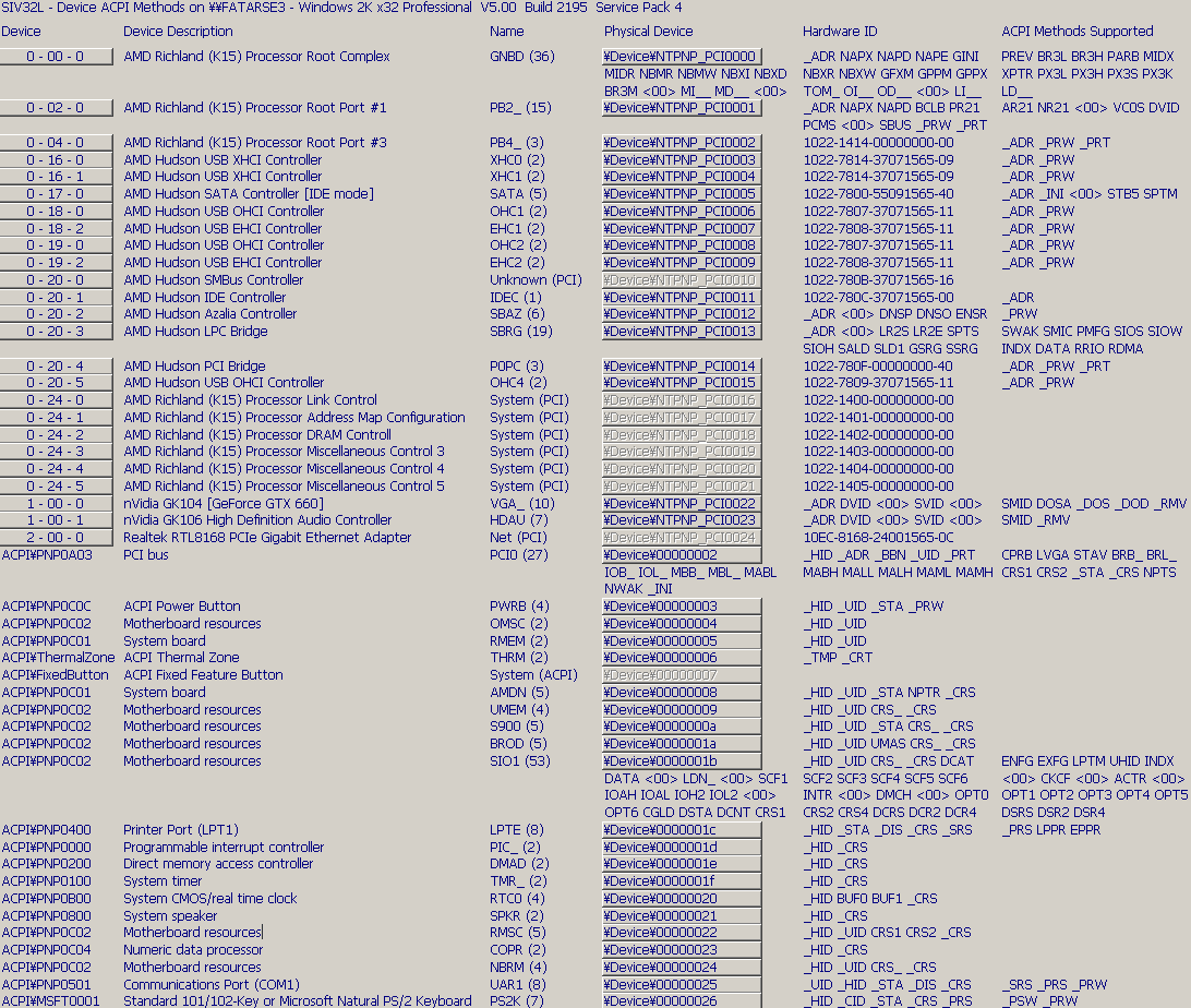
A patch to the imports data in STORPROP.DLL appears to bring back some settings that had gone missing under Device Manager properties for disks and disk interfaces. A picture is worth a thousand words:
|
2022 Dec 27 Windows 2000 extended kernel - properties page issues
A patch to the imports data in STORPROP.DLL appears to bring back some settings that had gone missing under Device Manager properties for disks and disk interfaces. A picture is worth a thousand words:
|
|
2022 Nov 19 power consumption comparison
My old board, the Biostar A770-A2+, was never too much of a power hog. Back in 2008 it was configured with an Athlon X2 4850e, and a GeForce 7600GT (passively cooled). In 2022, it has an Athlon II X2 280, and a GTX 650 Ti. These run hotter under load but the 650 Ti uses less energy at idle than the 7600 GT did. My new(er) board, which I obtained in 2021, is the Biostar Hi-Fi A88S2. I ended up going with the FM2+ platform because, ironically, I did NOT want integrated graphics. It was much easier to find an FM2/FM2+ board and a CPU without integrated graphics (even if it exists on the die and is merely disabled) than it was to find an AM3+ board without chipset graphics. (Intel likewise has made very few CPUs without integrated graphics, and getting Windows 2000 to run on an AM4 board is a challenge for a later date.) The new board has somewhat better performance, but power consumption is also reduced. Going into standby was nearly pointless on the old one, but now it uses so little power I can't even measure it with much accuracy. (Note that both systems were measured with two HDDs and a DVD drive connected) |
|
2022 Nov 14 Modular-NOWUT version 0.30 release
Many changes in this one: fixes, optimizations, new features, and the introduction of "Modular-NOWUT" which is different than Multi-NOWUT in that a partial build is now possible with support included for some CPUs but not others. Compiling NOWUT 0.30 requires at least GoLink 1.0.4.1 (from Go Tools website) and LINKBIN 0.30 (included), because it now uses multiple data sections that have to appear in a certain order. Having NOWUT 0.30 also helps... though it should be possible to build 0.30 with 0.29 (except for 8086) if 'usefastbase' is commented out and the few IFCPUxxx statements are changed back to the old syntax. 'SH4' and 'dcast' targets and a small Dreamcast test program were added. Check the documentation. Download the complete archive. |
|
2022 Nov 6 "Can it run Crysis?"
I used the old Crysis demo version to run some benchmarks a while back. Oddly, it would not run on the FM2+ system. I assumed the reason would be something dumb like missing registry keys from just copying the directory from one system to the other without running the installer again. Later, when I actually swapped the HDD over and booted the same Windows install, and Crysis still didn't run, I decided to investigate with the debugger. Turns out the game was trying to execute 3Dnow! instructions which were dropped by AMD CPUs after Phenom II, though rather than showing the usual 'illegal instruction' error dialog it would just fail silently. People on the interwebs already discovered this a long time ago and released a patched CrySystem.dll to fix it. But there was a problem. CrySystem.dll was already patched back in 2007 to get the game running on Windows 2000. I need both patches at the same time, otherwise it still won't run. Luckily, I was able to find the exact routine that was patched for the 3Dnow! fix and apply the same modification to the DLL that was fixed for Windows 2000. The long string of NOPs made it stand out a bit. 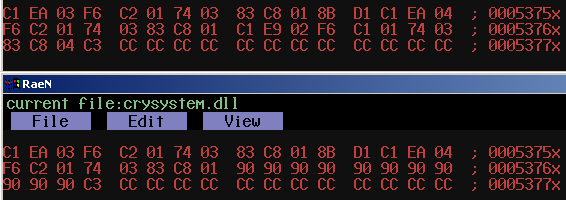
Using the VOGONS standard of 1280x1024, no AA, 'high' quality, and 9 o'clock, I scored 63.9fps at 3.9GHz. |
|
2022 Oct 26 AMD FX-770K
FX-xxx is one of the less common badgings of AMD's socket FM2/FM2+ APU chips, which also sold as Sempron, Athlon X2, Athlon X4, and A4/A6/A8/A10. The FX-770K is a 28nm 'Steamroller' architecture without integrated GPU functionality, making it similar to the Athlon X4 860K, 760K, and so on. But this chip is rated at 65W TDP instead of 95W or 100W. So I expected it to 1) use lower voltages, and 2) be a good overclocker when installed in a 100W-capable motherboard. I was wrong on the first point, as the voltages are nearly identical to my 760K. 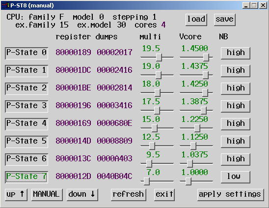
Just the clock speeds are a bit lower (3.5-3.9GHz vs. 3.8-4.1GHz for the 760K). It doesn't seem like it would be enough to drop the TDP all the way from 95W to 65W. But measurements show that this CPU consumes less power even at the same frequency and voltage as the 760K. Credit that to the new architecture, I guess. As for overclocking, it can easily run at the higher base frequencies used by the 760K without any voltage tweaking. P-ST8 works on this CPU as long as 'C6 mode' is disabled in the BIOS. If C6 is enabled, then the CPU throttles automatically and the p-state will read back as #7 instead of what was previously set. While I've never found integrated graphics to be appealing in the slightest, I thought the FM2 platform's replacement of separate 'north bridge' and 'south bridge' chips with an FCH and moving PCIe onto the CPU was a nice simplification. There is a downside, however. Swapping CPUs on AM2/AM3 is no big deal at all, but on FM2 it triggers Windows to reinstall a whole bunch of drivers :p |
|
2022 Oct 25 making a 'boot shim'
My recent post about patching ACPI tables at boot time raises the question of how exactly one can run code before booting any OS. Turns out that it isn't very difficult. The first thing that is needed is a boot sector which will load your code. You could make your own, but repurposing an existing one is much quicker. In my case, I made a copy of a Windows 2000 boot sector and changed the 'NTLDR' string to 'TTLDR'. An easy one-byte patch. That will make it load something else instead of NTLDR. NTLDR gets loaded at the $2000 segment and begins execution at an offset of 0. The CPU is in real mode and the boot sector obviously doesn't do any relocations, so what are we going to execute? A DOS-style .COM program would almost work, except that these expect to begin at an offset of $100 instead of 0. But this is easily fixed by putting a far-jump at the beginning of the program which jumps to segment $1FF0 and offset $105 (where the 5 accounts for the length of the far-jump instruction itself). Also unlike a normal DOS program, you can only use BIOS INTs since DOS isn't present. After TTLDR executes, I want to restart the normal booting process. I could load another boot sector, but then I don't even need to because there is already one still present in memory at $7C00 (segment 0). All I need to do is undo my one-byte patch, change TTLDR back to NTLDR, and then do a far-jump to $7C00. Job done. |
|
2022 Oct 24 a humble text/hex editor - first release
Back in 2015 I had a plan to make a web browser (or something vaguely like one) in FreeBASIC using the same UI code as MBFAST and IMGTOOL. That plan died when the HTTPS fad came along. Later I improved the editing features and fixed some of the bugs and the program became a text/hex editor instead. Fixing the remaining problems with it, with or without stripping out unnecessary browser stuff (URL parsing, image loading, etc.) seemed like too large of a task though. Eventually I decided to make a new one in NOWUT instead. 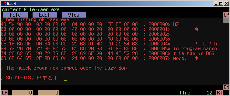
RaeN. Looks like the old FreeBASIC program even though it uses my (currently WIP, closed) NOWUT GUI library from ISCM and P-ST8. So far there is only a Win32 build. It works similarly to the MS-DOS Editor. I also hacked in some Shift-JIS support, which is reasonably compatible with the concept of a fixed-size character cell. (The old 'web browser' could handle different font sizes but RaeN does not.) Much to my surprise, since I didn't have to do anything to make this work, is that Shift-JIS can be ENTERED in RaeN using the IME under Windows 2000 when set to the Japanese code page. Wikipedia editors seem to think that EUC-JP is better because only bytes above $7F are used for multi-byte characters. I don't see this as being an issue at all. My beef with Shift-JIS (aside from choice of characters and the empty ranges) is that there are bytes which are allowed as both first and second byte. If they had reserved 62 values as possible first bytes, disallowed those as second bytes but allowed everything else other than $00-$1F, they could have encoded 10,000 characters all while making it possible to look at ANY TWO consecutive bytes in a string and know whether a complete, properly aligned, two-byte character existed there. EUC-JP also fails at this, and introduces 3-byte codes which break the one-byte-per-character-cell correspondence. Unicode is, of course, a complete disaster. The ASCII font is built in, but JIS full-width characters are in a separate JISFONT.BIN file. Making a bitmap font with thousands of characters would take too long, so I just made a text file showing the whole character set like this. Then I took a screenshot and turned that into a 16-bit x 15-line bitmap font . |
|
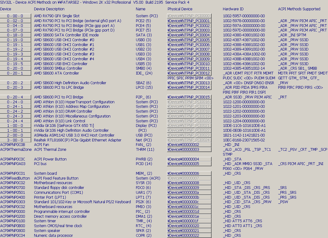
2022 Oct 17 digging into ACPI a bit
ACPI tables are generated during the BIOS/UEFI booting sequence and placed into RAM for the OS to find them. (Though maybe older PCs or other devices could have static tables inside the firmware itself.) The OS can find these by searching for a "RSD PTR " in the first 1MB of address space. This shows up in the traditional BIOS area at $Fxxxx 
In this case there is a 32-bit pointer to an RSDT structure at $DC843028, followed by a 64-bit pointer to an XSDT structure at $DC843080. Windows 2000 only uses RSDT. The XSDT is basically the same thing as RSDT but with 64-bit pointers in place of 32-bit pointers. Both of these structures point to additional ones such as HPET, MCFG, FIDT, FPDT, FACP, and so on. This system has 8GB of RAM installed. On a system with 2GB installed the RSDT was at $7FFExxxx, and with 3GB installed it was at $BFFExxxx. I dumped the data to a file with a DOS program by (1) calling the XMS driver through the INT $2F interface to enable the A20 gate and then (2) switching to the so-called 'unreal mode' which allows 32-bit addressing inside 16-bit code. 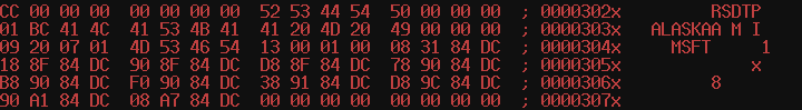
Some of these tables, like DSDT, contain ACPI Machine Language code which can be compiled/decompiled with Intel's IASL utility. My idea is to remove some troublesome pieces of code and use a boot shim to install the modified ACPI table before loading Windows 2000, thereby avoiding random boot failures due to a frozen video driver. While searching for info I ran across a post from someone else who had the same idea of patching ACPI tables at boot time |
|
2022 Aug 27 issues with Nintendo 64 cartridge simulator
After further experimentation, I found that the SDRAM was not really working at 110MHz. I think the only reason the N64 could boot from it is because there was enough time for the SDRAM to be read more than once for each N64 bus cycle. The first read always failed but subsequent ones would succeed. Based on the SDRAM datasheet, none of its timings should have been violated, but the capture of the read data by the FPGA would have had only 1.7ns of setup time which I guess may not be enough for the FPGA. So I took the clock speed back down to 80MHz for reliable SDRAM operation. I received a CP2104 USB-serial dongle, and found that the drivers for this also cause a BSOD :) I supposed if I want USB-to-FPGA communications I'll have to write my own driver. But at this point I'm already done with my N64 project so the necessity is not there. |
|
2022 Aug 11 preliminary Verilog for a Nintendo 64 cartridge simulator
I use a simple protocol for FPGA - PC communication. Sending an 'A' followed by three bytes sets an address. Sending a 'W' followed by 64 bytes writes data to the SDRAM. Sending an 'R' causes the FPGA to read 64 bytes from the SDRAM and send it back (for verification or whatever). There is also 'debug data' that the FPGA can send to the serial port when the N64 is doing things. (As of right now it just sends out the low word of each address accessed, to the extent that the serial connection can keep up with this data stream.) So the basic idea here is to 1) configure the FPGA, 2) use serial link to send a ROM image from the PC, 3) power on the N64. Sometimes I can even load a new ROM while the N64 is on and just press reset. The PC/serial interface and N64 (cartridge) interface are active at the same time and compete for time to access the SDRAM. The N64 slot doesn't have any kind of 'wait' signal and expects the cartridge to always be able to respond within the same timeframe (although this is configurable through software to some extent, and by using a byte in the ROM header). The usual READ pulse is 300ns though, which is fairly generous. So I'm not sure that there is any scenario where the SDRAM controller would fail to provide the data in time, at its current 110MHz clock. N64 code always runs from internal RAM rather than cartridge ROM. The cart interface is pretty limited, as I soon found out. In the current release of NOWUT, the linker uses the $90000000 address region for initialized data. This works in some N64 emulators but doesn't work at all on the real N64! It instead crashes immediately. (LINKBIN will have to be changed back to how it was before, basing everything in RAM.) |
|
2022 Jul 14 INFLATE routine in NOWUT
This is source code for an example program to expand a .VGZ file (compressed with GZIP) into a .VGM file. The routine quickly decompresses data from a file into a memory buffer. (10KB/sec on an 8MHz 286, and 13KB/sec on a 10MHz 68000.) It doesn't actually check the various flags in the GZIP header or handle block types other than 2, but it worked on the .VGZ files that I tested! |
|
2022 June 5 ACPI weirdness
|
|
2022 May 18 NOWUT version 0.29 release
Relatively minor changes/fixes in this release. The Windows JPEG decoder example now runs under Windows 3.1 with Win32S installed. There is also an example of a Windows NT device driver. Check the documentation. Download the complete archive. And be sure to get Go Link from Go Tools website. |
|
2022 May 15 How about that Z280?
The Zilog Z280 is an old sort-of-barely 16-bit extension to the classic Z80 CPU. It has additional instructions, an optional 16-bit-wide data bus, a 256-byte cache, and on-chip peripherals. Not bad, right? But it doesn't seem to have enjoyed much popularity back the '80s. However, in the current era it is making a small comeback in the form of some homebrew projects: Z280 on Hackaday Z280 on HacksterThe Z280 is in a special category that makes this kind of project interesting to me. I've had about enough fun already with 8-bit CPUs over the years, and wouldn't go to the trouble of making my own board just for more of that. But this is a 16-bit CPU... with respectable double-digit clock speeds. It's also unusual. I don't already own a system containing a Z280. Can't even name one for that matter. Crucially, it comes in a PLCC package which means it could go in a socket on a board that I could design and assemble myself. And I have my own ideas about what such a board should look like. Whereas the Z80 instruction set was a (slightly-hackish) extension of the 8080, the Z280 is an extension of that extension, so it's a bit messy. Prefix bytes are used to expand the opcode space, causing code density to suffer somewhat, but there are new arithmetic instructions (including multiply and divide) and new addressing modes (like the much-needed 16-bit indexed mode) which look useful. Interestingly, the Z380, which is a 32-bit extension of the Z80, completely scraps the Z280 extensions and begins anew. Then the EZ80 scrapped everything again and extended it in yet another direction. What is sadly missing in the Z280 is the ability to directly address more than 64KB. It does have the ability to split code and data address spaces into two separate 64KB areas, making it somewhat like the 8086. Though there is no separate segment for the stack, and updating the MMU registers to change pages is even less convenient than updating segment registers on the 8086. I compile NOWUT code for an 8086 with a pseudo-linear address space by updating segment registers on the fly, but the code ends up being bloated to twice the size of 386 code. Thinking about how to pull this off on a Z280, I think it would require another bank switching mechanism, implemented outside the chip, which could swap out a 32KB area with one OUT instruction. (and the cache would be used only for instructions, to avoid coherency issues.) A post on retrobrewcomputers said that the Z280 in 8-bit bus mode, on a clock-for-clock basis, comes in a bit slower than a plain Z80. I'm having a hard time figuring out how this would be possible at the full bus frequency (1/2 and 1/4 dividers can also be configured), since the manual specifies 3 cycles for a memory access and refresh cycles are now optional. The instruction timings listed are also faster than those of the Z80. I would rather use the 16-bit Z-BUS mode in any case, for better performance. The Z-BUS is meant to be compatible with the Z8000. This was another Zilog CPU, tragically obscure, despite a better architecture. It's also BIG ENDIAN. So it seems that the Z280 in Z-BUS mode expects the byte with the lower address to appear on data lines 8-15, and the byte at the next address to appear on 0-7. Like a big-endian CPU. While the Z280 continues to be a little-endian CPU. It's a bit strange. The on-chip UART is another source of consternation. The baud rate is determined by setting up one of the on-chip counters, clocked at CPUCLK/4, and further dividing its output by 16. So if your CPU was 12MHz, then that has already been divided down to 187.5KHz before you have the opportunity to configure your own divider to try to get close to a standard rate. For instance you could divide by 39 to get close to 4800bps, or 13 to get 14400bps, but anything more than that is not looking good unless you have chosen a different CPU clock. The UART configuration does have a mode without the 1/16 divider, but the manual says this about it: 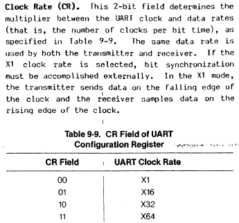
"synchronization must be accomplished externally." I guess this means that the data bits must line up with the clock edge? It might useful for a serial link between two Z280 CPUs on one board or something, but it's not going to work for RS232...I'm not sure how much I care about serial, since I can easily program a ROM and boot from that, although I don't know many times I'd end up re-programming the ROM before I get satisfactory code in there. And the 16-bit bus will likely mean either two 8-bit EEPROMs each time, or one 16-bit EPROM. Other interesting possibilities: |
|
2022 May 3 fully decked-out OPN card
|
|
2022 Mar 24 Stop programs from phoning home
I was running Wireshark one day, I forget the original reason, and I noticed that a game was connecting to remote IP addresses on the internet. This shouldn't be necessary for playing single player. I checked the game EXE's import list using CFF Explorer. It used WS2_32.DLL. This DLL is not listed in the Windows 2000 registry under "KnownDLLs". So I added a copy of it to the game's directory, used CFF Explorer to dump the code section, NDISASM to disassemble it, found the entry point for WSASocketA, and patched a few bytes so that the call would always fail. I chose that function because it was imported by the game by name (others were imported by ordinal). Now when I run the game there is no mysterious internet traffic, whatever it was for. |
|
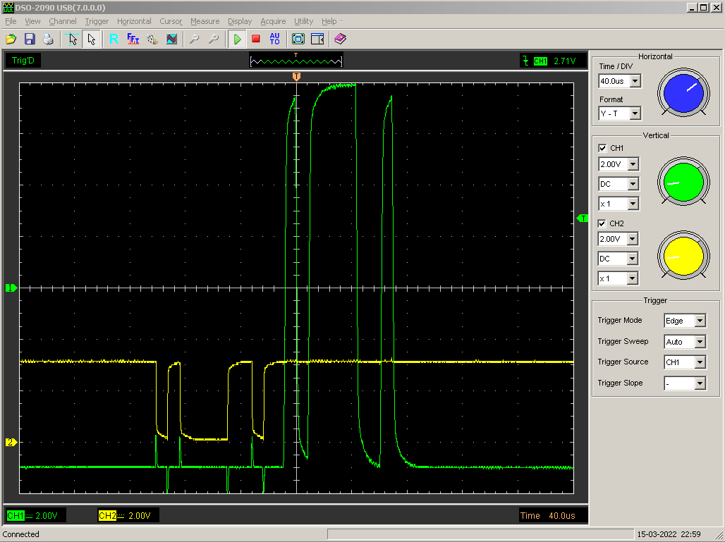
2022 Mar 16 RS232 working on the QMTECH board
I already got RS232 working on an FPGA with the Storm_I board, but that has a MAX3232 and a DE-9 connector right on it. The QMTECH board didn't, so I had to build my own interface. I used a MAX232E, with a voltage divider (2.2K and 1K resistors) on the output pin feeding the FPGA, since the 232E is a 5V chip. I saw that the 232E has two separate channels, and so I thought MAYBE since I was only using one channel I might not need all of the capacitors installed? That was wrong though. With the 'C2' capacitor missing the RS232 voltage could only go positive and not negative. It really does need five capacitors :p
|
|
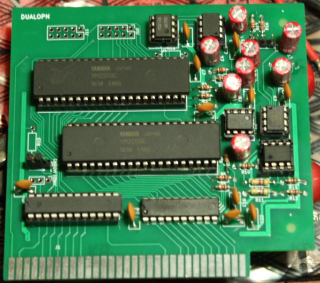
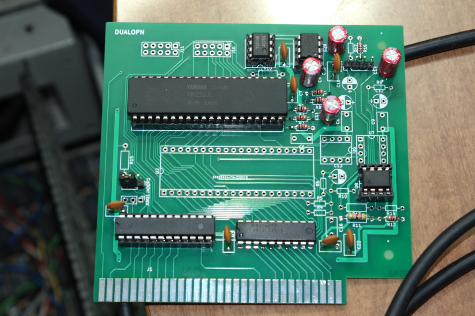
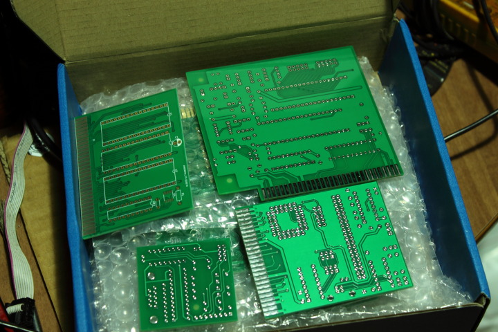
2022 Mar 16 Yamaha OPN on an ISA card
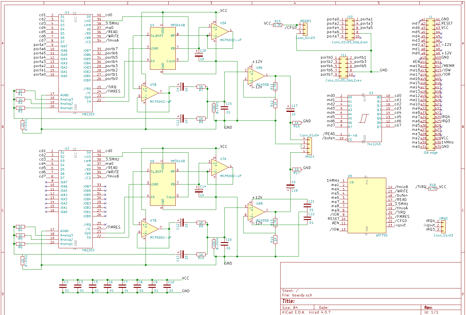
From my post on VOGONS:
As I discussed briefly in a previous posting, OPN is a nifty chip from the '80s which is basically a YM-2149 with FM audio synthesis added on. In addition to audio functions, it has a timer and bidirectional parallel ports. It was used in Japanese computers and arcade games and is the predecessor of the YM-2612 used by Sega. Putting a YM-2203 on an ISA card is what I chose as a random, fun project for my first PCB back in 2019. Unsurprisingly for a first PCB, it had some problems. I didn't have positive and negative voltage supply connected to the opamp. I didn't have a suitable clock feeding the YM-2203. SSG sound didn't work. The IRQ only worked once and then stuck high. And so on. Fast forward to 2022, and since I already planned to order some other PCBs, I ordered a set of redesigned OPN cards too. This card has: Laying down a 'zone' on the rear copper was easy after I figured out how to do this in KiCad. Of course, I am using 4.0.7, and they have newer versions now which may work differently but I don't use them because they don't work on Windows 2000. The first thing is to leave off ground connections which exist inside the zone area because they'll be redundant once the zone is there (and they won't be be removed automatically). Then I choose the 'zone' tool, click the bottom-right corner of a rectangular area, followed by the top-right, top-left, bottom-left, and then the bottom-right again. It's possible to click on the edge of a zone (a one-pixel-thick line on my screen) to select it, at which point you can remove, redo, or edit its properties. Component selection was somewhat arbitrary, based on parts that I already had on hand. For instance I have a lot of 1K resistors, and 10uF and '103' capacitors. 1K resistor and a 10uF capacitor makes a low-pass filter with the corner at ~16Hz. 1K resistor and a 10nF (103) capacitor makes a high-pass filter with the corner at ~16KHz. Luckily that is an acceptable range for audio so these are the values I used. I have a few MCP6002 'rail-to-rail' opamps so I used those, with single 5V supply, for the Y3014 DAC. Then I used an RC4558 with +/-12V supplies for amplification. So I like the look of this board a lot more than the first one, but it was unfortunately also not without a few minor problems. I quickly discovered that it didn't work UNLESS a scope probe was connected in a certain place, LOL. Analog stuff is still fairly mysterious to me but it seems that the input to the RC4558 was floating up to 12V and staying there. Adding a 10K resistor to ground fixed that. The next problem was that everything was very high-pitched :) The ATF750 was supposed to output a 3.5MHz clock, but there was a problem with the Atmel WinCUPL code and it wasn't working as intended, so the YM-2203 was overclocked to 7MHz... After a bit of fumbling with the CUPL I got the proper 3.5MHz. Lastly, SSG sound was again not working, and the fix for this turned out to be adding another resistor. Other considerations: I'm still not quite sure about the orientation of C17/C18. Or maybe it would be better to use a non-polarized capacitor here? *shrug* I'm also thinking that maybe I should have put a current-limiting resistor between the ATF750 and the IRQ line, in case there was an IRQ conflict with another card. Though in the picture you can see I didn't even install the jumper for IRQ selection, as it's not strictly necessary to use the card. It's only there for timer interrupts, whereas in my quick-and-dirty VGM player that I got going on my 286 I just used the 8253 for timing. |
|
2022 Mar 2 XGecu T56 is here
After trying to use this programmer for the first time, it soon became clear what WINUSB is and why the DLL was missing before. WINUSB is a generic USB driver from Microsoft which can be used by devices that don't need to conform to any particular function standard (unlike, say, a USB keyboard or camera which the user would prefer to act like standard devices). WINUSB was supposed to be installed by the driver package that came with Xgpro, but it wasn't because the driver package is a disaster that doesn't work on Windows 2000. However, the drivers CAN be made to work. In the Xgpro directory, under drv\WINXP\x86 are two files: WdfCoInstaller01009.dll and winusbcoinstaller2.dll. These can be unpacked with 7Zip. Out of the first one you'll get a "Microsoft Kernel_Mode Driver Framework Install-v1.9-Win2k-WinXP-Win2k3.exe" As you can see, it even has Win2k in the name :) Run this and it will install some files and registry entries. Unpacking the second DLL will give you several files, including winusb.dll and winusb.sys. Unfortunately, I could not solve the puzzle of how to make it install. Trying to run update.exe results in a nonsense error about a missing file. I can copy the files to SYSTEM32 and SYSTEM32\DRIVERS myself, but I really need a winusb.inf, because it needs to set some registry entries and also because it is referred to by the xgpro.inf file. Later versions of Windows come with a winusb.inf file. So I modified one of those, and also modified xgpro.inf so it would work on Windows 2000. Voila! It looks like the next thing I might have to do is rig up a power supply. The T56 has a connector for a power supply but it didn't ship with one, under the theory that USB power is enough for programming single chips. But when I launch Xgpro the first thing it does is complain about low voltage. It wants at least 4.8V, and I am not even getting that much when measuring with my volt meter under no-load, LOL. If I plug it into a USB 3 port then I can get 4.81V and no error appears, but that is cutting it a bit close I think... |
|
2022 Feb 24 Obstacles
I received PCBs for several projects but don't have the parts to assemble all of them. MCP2221a is now suddenly out of stock :( Though I did have a 'plan B' already in case I couldn't get that chip to work. What is worse is that I assembled one board I did have all the parts for, with the last step being to program an ATF750 and plug it in. Turns out the problem that the EMP-11 had with 16V8s was not just with 16V8s, because it can't program an ATF750 anymore either (it definitely could before). I'm gonna say it's dead. Time to upgrade to an Xgecu T56. I downloaded the Xgpro software to make sure it can run on Windows 2000. At first it wouldn't due to missing WINUSB.DLL. What is this DLL and why didn't they include it in the download if it is required to run? Web search results for a DLL name are all inevitably SEO spam, so who knows. But I searched my own computer and found the file. It was included with the drivers for the ic2005 NEO PCE Flash card. Looks like it does run. 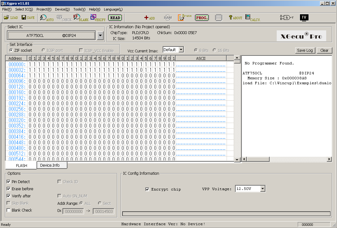
|
|
2022 Feb 10 FLY-VS-FLY source dump
This is NOWUT source code and assets for the Saturn 27th Anniversary game competition entry. FLYSRC.ZIP. The background images are photos taken with my DSLR, cropped and resized to 640x448, and converted to 256 colors using IMGTOOL. |
|
2022 Feb 9 Watch out!
This PLCC socket footprint that was bundled with KiCad has some issues. 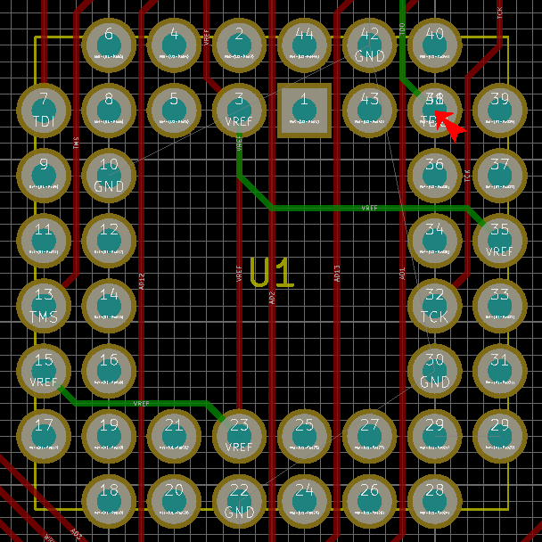
Pin 38 sold its land to pin 29 and moved in with pin 41. |
|
2022 Feb 8 Cartridges, FPGAs, and interesting chips
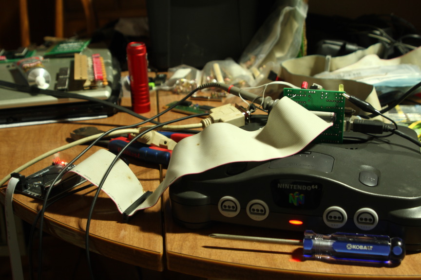
An important part of homebrew development for old game consoles is being able to run code on the real hardware. I have a TurboGrafx-16 card with flash memory, and a Genesis/32X cart that takes micro-SD cards for this purpose. But ever since I saw the price for an equivalent N64 solution, I've been thinking "How can I make my own N64 cart?" The N64 cartridge bus has multiplexed address and data lines, which doesn't seem like too much of a challenge. (There is that CIC doodad too, but I guess one could be harvested from an official game if needed.) It's also 3.3V. So I'm browsing 3.3V CPLDs and memory ICs on Mouser, but I don't want surface mount. There's basically nothing to be had that isn't surface mount. Then I had a better idea... I could just connect the QMTECH Cyclone IV board! That can interface with any 3.3V bus, and it has 32MB of SDRAM to store a ROM image. I would still need some way to transfer data into the SDRAM in the first place though. Come to think of it, this would be good for other projects too. The Storm_I board has a MAX3232 on it so I can do an RS232 link between the FPGA and a PC. I could connect a MAX (these come in DIP packages) to the QMTECH, but then again I'm not really happy with the 115Kbps speed limit. The FPGA UART can certainly run faster than that but I don't think the PC can. Although PC serial ports supporting 921Kbps apparently exist, mine is not one of them. Parallel port? That would mean a clunky DB25 connector with many wires, plus it's 5V. So... what about USB? It seems that every FTDI chip is surface mount. But I found something else which isn't: MCP2221a. (Not to be confused with MSD2225, my old favorite electric fuel pump...) Well, it's four times faster than the regular serial port. I'll take it. |
|
2022 Jan 18
NOWUT version 0.28 release
The major change in this release is the ability to compile for the N64's MIPS-based VR4300 CPU, as I had a sudden urge to try making N64 homebrew. The addition of another assembler and code tables has bloated the compiler a bit more, which is now hovering at ~100KB. At one point the 8086 build overflowed its 64KB code segment but I was able to cram it back in with some optimizations. Though this was a problem I've been expecting, and in the future I may make it so the compiler can be built with support for only certain CPUs rather than all of them, in case a smaller build is needed. Check the documentation. Download the complete archive. And be sure to get Go Link from Go Tools website. |
|
2022 Jan 18 Game soundtracks
Some games contain a soundtrack readily recognizable as common audio file formats like Ogg, Opus, or the like. Other times the data is somewhat hidden or uses a proprietary format. For instance, many games have an .XWB file full of audio compressed with Microsoft's old ADPCM codec (these can be extracted with a utility called unxwb). I've also seen several games from different developers that have a bunch of Vorbis audio packed into a .BRA file. 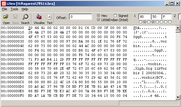
Here is a short NOWUT program that can extract these to individual .OGG files. |
|
2022 Jan 12 Saturn binaries
For the next release of NOWUT, I'm planning to change the base address used for Saturn binaries in LINKBIN from $06004000 to $06022000. The former is a default load address in Saturn USB and some emulators. 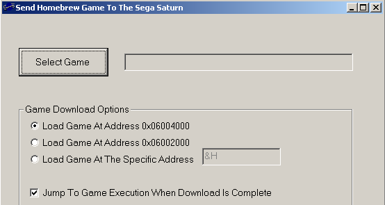
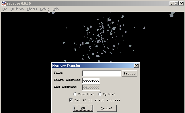
IP_GNU.BIN uses $06010000 which is even worse (though easily changed). The problem with these addresses is that they leave little room to load anything from CD. 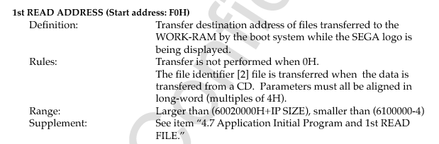
It seems that the initial loader executes from $06020000. So what happens when you load a file that writes over that address range? System crashes without ever jumping to your code. IP_GNU.BIN is 5KB in size, so loading at $06022000 does not overwrite it, and allows loading an 800KB+ file. |
|
2021 Dec 13 16V8 Programming = Verified
Two ATF16V8B chips that I programmed using ATFBlast (with a JEDEC file created in Atmel WinCUPL) tested OK via breadboard. 
|
|
2021 Dec 7 ATF16V8B programmer
Using the plans from this page, I rigged up a programmer for the ATF16V8B which connects to a PC parallel port. My device is similar to the "minimal" ATFblast schematic except moreso, because I use a PC power molex connector for my 5V and 12V supplies. I also rearranged the pin assignments to work with the 16V8 instead of the 22V10 as these have different pinouts ( detailed here). The 16V8 is only a 20-pin chip, though I mounted a 24-pin socket on my board because I have no 20-pin sockets. It seems to be working, as I was able to program two chips including one of the ones that failed in the EMP-11. The ATFBlast program complained about an incorrect PES, and I wonder if this is related to the problem with the EMP-11 software. Apparently the PES is supposed to contain an ID string, yet it is modifiable data so in practice it can contain anything. Doesn't make a lot of sense. ATFBlast has an "untested" feature for writing the PES. I tried it once and it did change the data, though reading it back did not match what I attempted to write. ATFBlast can simply ignore the PES and program the chips anyway, which seems like a sensible way to handle the situation. 
|
|
2021 Nov 30 revisiting Radeon drivers in Windows 2000
I previously mentioned trying Catalyst 11.7 from BWC's site to run a Radeon 5670. While compatibility with DX9 games seems to be OK, OpenGL support is not too hot. This is unfortunate, as with DX10/11 not being available on Windows 2000, OpenGL is the only newer API available. Catalyst 11.7 also only supports cards up to the 6000 series. Catalyst 12.4 is somewhat better in terms of OpenGL (it runs Unigine Heaven with some graphical glitches) but it can freeze the system when attempting video playback (same deal for Catalyst 13). When running in debug mode I saw that there are some messages emitted when this problem occurs: Error[PP_PowerPlay]: rv770_hwmgr.c[3653] -- Assertion '(PP_Result_OK == result)' has failed: Failed to unregister high thermal interrupt! Error[PP_PowerPlay]: rv770_hwmgr.c[3657] -- Assertion '(PP_Result_OK == result)' has failed: Failed to unregister low thermal interrupt! Error[PP_PowerPlay]: eventinit.c[724] -- Assertion '(PP_Result_OK == result)' has failed: Failed to unregister interrupt for CTF event! Error[PP_PowerPlay]: eventinit.c[730] -- Assertion '(PP_Result_OK == result)' has failed: Failed to unregister interrupt for vbios events! Error[PP_PowerPlay]: rv770_clockgating.c[409] -- Assertion '(PP_Result_OK == result)' has failed: Failed to unregister graphics busy interrupt. Error[PP_PowerPlay]: rv770_clockgating.c[412] -- Assertion '(PP_Result_OK == result)' has failed: Failed to unregister graphics idle interrupt. Since there is a Catalyst 14.4 for Win XP, I wondered why this couldn't be used in Win 2000. The .INF file needs modification for the driver to install, and upon booting ATI2MTAG.SYS will load but ATI2DVAG.DLL does not load and the screen is stuck in standard VGA mode. After more hunting with the debugger, I found that ATI2MTAG allocates memory for some data structure with a size of $54 bytes, the size then being recorded at the beginning of this block. Later, some unknown Windows code checks the size, expecting it to be $50, and returns an error code $C0000059 STATUS_REVISION_MISMATCH. That seems to be the reason that ATI2DVAG was not loading.
I tried changing the $54 back to a $50 to make Windows happy, but then I got a BSOD instead. Code 1E KMODE_EXCEPTION_NOT_HANDLED due to a null pointer reference in one of the power-related OS routines. No progress on this front :( |
|
2021 Nov 27 ReactOS...
ReactOS can run inside a VM, but running it in a VM is boring and slow, like everything else in a VM. I've tried to run it on real hardware before but it usually fails. The only time I got an OS that would actually boot was once when I installed on a Pentium III with i8xx chipset. My last attempt was a year or two ago, on a Pentium M laptop. So I thought I'd give it another go, but on a desktop socket FM2 system this time. Installing ReactOS has always been badly complicated by the lack of a DOS setup program. Windows 9x has a SETUP.EXE, Windows NT/2K/XP have WINNT.EXE, ReactOS has nothing. It can't be installed from HDD. Even if you trick the setup program into booting from HDD, it doesn't work because they put the installation files in a directory called 'ReactOS' which is the same directory name that they want to install to. So my plan this time was to boot the ISO in Virtual PC and do the 'text mode setup' (first part) and then copy the resulting newborn ReactOS installation from the Virtual PC disk image to the C:\ FAT32 partition in a real PC. Will it work??? I want ReactOS to be an option on my existing NTLDR boot menu. I don't want to let ReactOS rewrite the boot sector because I don't want to get stuck in a situation where I can't boot NTLDR anymore. Then I'd have to take the harddisk out and connect it to another system to straighten it out. Inside the ReactOS ISO is a FAT32.BIN which can be used to make a boot sector manually. The BPB data needs to be populated before it becomes usable. Namely, the sectors/cluster value at offset $0D and some other stuff from $10 to $4F. I copied it right from my existing FAT32 boot sector (sector 63 of the HDD). Then FAT32.BIN can be placed in C:\ and referenced in BOOT.INI. However, it is 1024 bytes which means it is actually 2 sectors. The second one needs to go somewhere too, because NTLDR (or the MBR code) will only load one sector. I disassembled the code and found that it loads the second sector from the location 14 sectors after the first one, ie. the main boot sector is in #63 so the second one needs to be in #77. This location doesn't conflict with the sectors used by Win98 or 2000 which is good. So I used a sector editor to put the second 512 bytes of FAT32.BIN on my HDD, then rebooted and selected the new ReactOS option in my NTLDR boot menu. I received the message "error opening freeldr.ini" Of course, I already had copied FREELDR.INI to C:\ along with FREELDR.SYS itself. So why the error? It so happens that a more helpful error message was also transmitted via the COM1 port. It read: (C:\buildbot_config\worker\Build_MSVC_x86\build\boot\freeldr\freeldr\disk\partit ion.c:186) err: Too many bootable (active) partitions found.LOL. Seriously? I disassembled FREELDR and found that yes, it counts bootable partitions and fails if there is more than one. To work around this bug, I simply tweaked my partition table, temporarily making the other partition non-bootable. Then I tried to boot ReactOS again. This time it started to boot. Showed the ReactOS logo. Switched to the VESA screen mode. Then... BSOD. (base\services\umpnpmgr\install.c:112) Installing: PCIIDE\IDEChannel\4&d0ea710f&0
(ntoskrnl\io\pnpmgr\pnpres.c:154) IopFindPortResource failed!
(ntoskrnl\io\pnpmgr\pnpres.c:417) Failed to find an available port resource (0xf090 to 0xf097 length: 0x8)
(ntoskrnl\io\pnpmgr\pnpres.c:468) Unable to satisfy required resource in list 0
(ntoskrnl\ps\thread.c:119) PS: Unhandled Kernel Mode Exception Pointers = 0xF78C1628
(ntoskrnl\ps\thread.c:126) Code c0000005 Addr 8047BD66 Info0 00000000 Info1 00000000 Info2 00000000 Info3 F78C1AC8
*** Fatal System Error: 0x0000007e
(0xC0000005,0x8047BD66,0xF78C1A9C,0xF78C1728)
Better luck next time.
|
|
2021 Nov 17 PAL fail
I have a Needham's EMP-11 programmer which I have used to read/program various types of ROM chips and some ATF750C. I was seeking a simpler device for a project where an ATF750 would be overkill, and so I obtained a handful of ATF16V8B. These are listed in the EMP-11 device list and programming software, but don't seem to actually work. I can put in an ATF16V8B and read it (and get all '1's). Attempting to erase or program a chip fails, and every operation thereafter will fail with "incorrect device ID" for the chip in question. Selecting the option under preferences to ignore the device ID has no effect. I don't know if the chips are being trashed during this process but they clearly will not work with the EMP-11. Lame. |
|
2021 Nov 10 NOWUT version 0.27 release
Most of the work for this release went into floating-point support. It is still not complete, but variables can be marked as FP with a new '.fd' tag and assignments like this are now possible: area.fd=radius*radius*3.14159 Having more than four decimal places no longer generates an error, though there will be a warning if digits are dropped due to lack of precision. You can go to nine decimal places when compiling from 386 platform (which is the only platform that implements FP at this point anyway). There is a short FPTEST program to demonstrate the parser's current capability. Another feature addition is the 'ea' special symbol (let's say it stands for Effective Address). The lack of being able to do fancy address calculations with an indirect address as the base has been a noticable hole in the language. Now I've settled on a way to do it without any radical new syntax. [baseaddr+offset+$14].w=0 ; ever wish that this was allowed? ea.w(baseaddr+offset+$14)=0 ; now it can be done this way! This avoids having to calculate the address and store it in another variable first. Check the documentation. Download the complete archive. And be sure to get Go Link from Go Tools website. |
|
2021 Sep 23 The video timing problem
On 1980s hardware you could read some hardware register and determine whether you were in the vertical retrace period or maybe even the exact scanline you were on. Maybe you could even configure an interrupt to happen at a particular time. This made timing relatively easy. What do we have on 21st century PCs? We have a bunch of different timers that count at different frequencies, all unrelated to video refresh, and under OpenGL we have wglSwapIntervalEXT. This is a meager toolbox but it's all I've been able to uncover so far. Meanwhile, the demands are also greater. Not only is it useful to be able to synchronize a program with the display, it is also desirable to handle variable framerates. The monitor refresh rate could be anything. The framerate could drop due to performance reasons. Or maybe you want to run a benchmark and let the framerate go as high as possible. Last but not least, after each frame is rendered and the thread is waiting to begin the next one, it is good to have the thread go idle and surrender the unneeded CPU time rather than pegging a CPU core at 100% while it waits. I put my rendering code into its own thread so it would be unaffected by window messages or audio related duties. Then I tested four different strategies in my game engine, on five different systems. Strategy 1: For this one, vsync is turned OFF with wglSwapIntervalEXT. The rendering thread pauses itself after each frame with a call to WaitForSingleObject. It then becomes unpaused by an auto-reset event which is signalled by the multimedia timer (timeSetEvent) configured to run every 16ms. The result is a framerate capped at roughly 60Hz, but not synchronized with the display. The CPU is allowed to go idle. Overall, not a bad option. This was the only strategy that produced the same results on every test system! Strategy 2: Here I turn vsync ON, and do not call WaitForSingleObject. I just let the thread run wild and hope that OpenGL and/or the video driver will do what I want and put the thread to sleep as appropriate. This strategy succeeded on systems 1 and 4, producing perfectly synchronized screen updates and low CPU load. On system 2, it drove a CPU to 100% load. System 5 was unique in that it put both CPU cores at 100% load. On system 3 the video was synchronized and the CPU load was low but a different problem appeared. The time between frames as measured by QueryPerformanceCounter varied wildly, so moving objects in the game suffered from horrible jitter. Strategy 3: This is the 'benchmark' mode. Vsync is turned OFF, and the thread is allowed to run wild. The results are mostly expected. Everybody has a CPU core maxed out (both cores on system 5) and stupidly high framerates. However system 3 appeared to have jitter sometimes but not always. I couldn't really nail it down. Also, on system 5 when running in OpenGL 1.x mode (but not 3.x mode) it ignored the vsync setting and continued to cap rendering at 60Hz. Strategy 4: This one is the same as #2 except I replaced glFlush with glFinish. That solved the jitter on system 3, but also caused the CPU loads to go to 100% again (both cores on system 5). I did not find a silver bullet. |
|
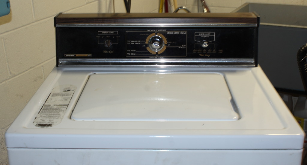
2021 Sep 8 Something a little different
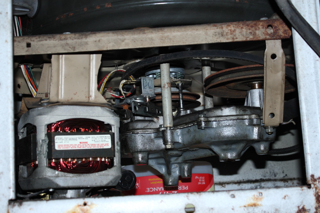
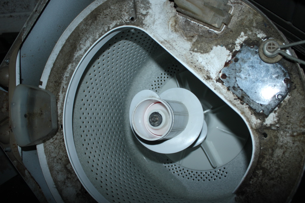
Retro machine? Yes. Computer? Ahem... maybe it is a sort of mechanical state machine with three states. In any case, this is a Whirlpool belt-drive washer sold under the Kenmore Heavy Duty label, model number 110.82081110, produced around 1980 AFAICT. It had been misbehaving a bit lately.
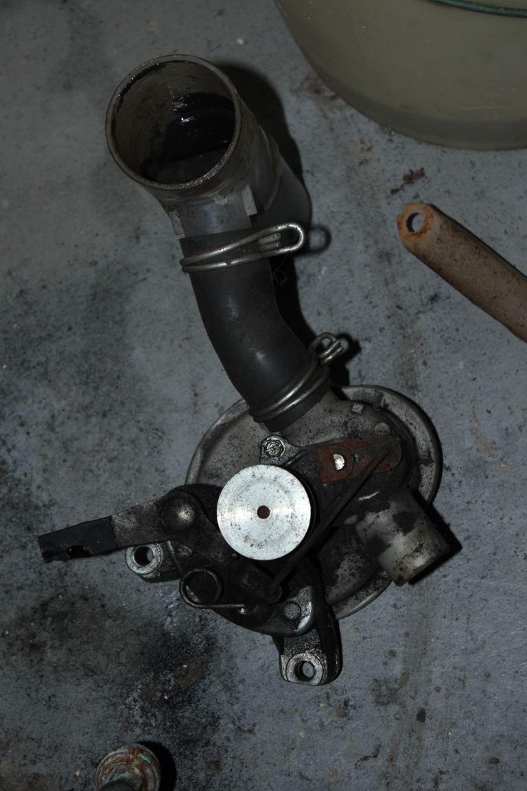
The third state is "spin mode" and this occurs when the left actuator engages. The left rail slides forward and allows a post to drop. The spring-loaded plate above it also drops and the clutch mechanism above the center pulley engages so that the washer's drum will spin with it. Note that the red wire on the left actuator leads to the door switch. It is disabled (no spin mode) when the door is open. See the black plate with one screw in the center, holding down the two rails? The gearbox oil can be refilled through that bolt hole.
While reinstalling, I noticed that this bolt securing the gearbox (closest to the front of the washer) goes through a spacer. Removing that one bolt and spacer ought to allow installing a new belt without removing everything else (though it would still need to slip between the clutch release plate and post). |
|
2021 Aug 28 368-byte Toadroar demo
Having fixed many bugs in my CPU core, I was able to port some old x86 code to Toadroar assembly and get it running on the QMTECH FPGA dev board. The CPU is running at 75MHz but memory latency is holding it back some, so it is only able to fill the 256x224 RGB screen at about 6fps. If I get around to adding an L1 cache, at least I have something to use as a benchmark :) noisy video recording from CRT |
|
2021 Aug 21 Cubemaps 2: Matrix Madness
I had to revisit cubemaps after changing the projection matrix used in my renderer. I changed the matrix because the old one was funky. I had suspected it for a while, but it was hard to be certain because of lingering doubts over which reference material was showing transposed vs. non-transposed matrices. Finally, I made test code that called gluPerspective and read back the matrix data with glGetFloatV. dd 1.299038 0 0 0
dd 0 1.732051 0 0
dd 0 0 -1.002002 -1
dd 0 0 -200.2002 0
This confirmed that my old matrix was not good. That, and the fact that it had excessive Z-fighting problems. Of course, fixing the projection matrix broke everything else, which had been designed around the funky one. Getting the cubemap to render again was not too hard though. texcoord3=mat3(purerotate)*position; gl_Position=vec4(projmatrix[0][0]*position.x,projmatrix[1][1]*position.y,1.0,1.0); The texture Z coordinate no longer needs to be inverted. As for the projection matrix, it turns out that the only relevant components in it are the ones related to the viewport size/aspect. So in the shader I just use those directly. callex ,gltexcoord3f, 1.0, 1.0,-1.0
callex ,glvertex3f, 1.0, 1.0,-1.0
callex ,gltexcoord3f, 1.0,-1.0,-1.0
callex ,glvertex3f, 1.0,-1.0,-1.0
callex ,gltexcoord3f, 1.0,-1.0, 1.0
callex ,glvertex3f, 1.0,-1.0, 1.0
callex ,gltexcoord3f, 1.0, 1.0, 1.0
callex ,glvertex3f, 1.0, 1.0, 1.0
OpenGL 1.x is the same thing. Flip the texture Z coordinate sign, and instead of using the projection matrix as-is, build a separate one like this: dd 1.299038 0 0 0
dd 0 1.732051 0 0
dd 0 0 1.0 0
dd 0 0 0 1.0
|
|
2021 Jul 25 Cubemaps
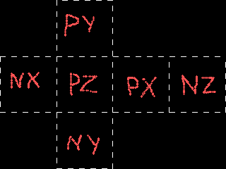
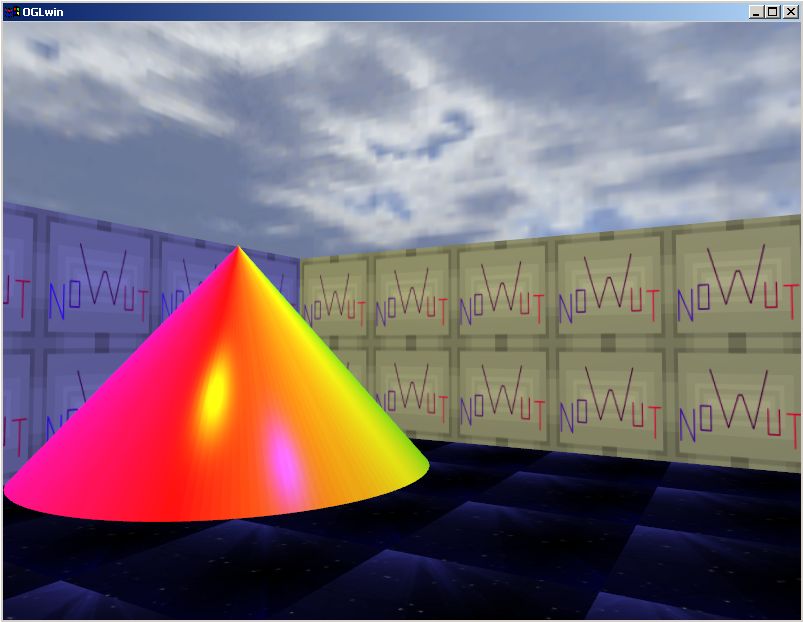
So I'm working on a 3D game engine in NOWUT. Currently it can render using the OpenGL 3/4 API with shaders, or the old 1.x API without shaders, because why not? There is a lot of common code between the two, and it's not clear at this point whether my plans for the game will preclude supporting older hardware. After getting some rudimentary models to render with a basic lighting configuration, I wanted to add a skybox. I didn't know how to do this in a game where the camera can look up and down, so I did a search and came up with the answer: cubemaps.
Looking at diagrams like this one and reading various descriptions that made it sound like one is rendering a giant cube around the outside of an environment made it hard to understand how this could work. Turns out, that's not what it is. The term 'cubemap' is really a misnomer and this doesn't have much to do with cubes at all. A cubemap has six textures, but they don't correspond to any flat surface. Instead, each texture corresponds to a direction. In the game, when you look straight up you'll see the "positive Y axis" texture. Depending on your field of view you might see only part of it, or you might see parts of the other textures where they meet the edges of the PY texture. The first step to rendering a skybox in OpenGL is to load the cubemap texture. This is the same in both old and new APIs: callex ,glgentextures,cubetex.a,1
callex ,glbindtexture,cubetex,$8513 ; gl_texture_cube_map
callex ,gltexparameteri,$812F,$2802,$8513 ; TEXTURE_WRAP_S = CLAMP_TO_EDGE
callex ,gltexparameteri,$812F,$2803,$8513 ; TEXTURE_WRAP_T = CLAMP_TO_EDGE
callex ,gltexparameteri,$812F,$8072,$8513 ; TEXTURE_WRAP_R = CLAMP_TO_EDGE
callex ,gltexparameteri,$2601,$2800,$8513 ; gl_linear, mag_filter
callex ,gltexparameteri,$2601,$2801,$8513 ; gl_linear, min_filter
callex ,glteximage2d,testcubepx,$1401,$80E0,0,256,256,$1908,0,$8515 ; $1401 = bytes
callex ,glteximage2d,testcubenx,$1401,$80E0,0,256,256,$1908,0,$8516 ; $80E0 = BGR
callex ,glteximage2d,testcubepy,$1401,$80E0,0,256,256,$1908,0,$8517 ; $1908 = RGBA
callex ,glteximage2d,testcubeny,$1401,$80E0,0,256,256,$1908,0,$8518
callex ,glteximage2d,testcubepz,$1401,$80E0,0,256,256,$1908,0,$8519
callex ,glteximage2d,testcubenz,$1401,$80E0,0,256,256,$1908,0,$851A
Rendering it correctly proved to be tricky. I have the third edition OpenGL book which covers version 1.2, but cubemaps were introduced in 1.3. So I had to do more searching online and shuffle matrices around and flip coordinate signs back and forth until something worked. callex ,glenable,$8513 ; gl_texture_cube_map
callex ,glbindtexture,cubetex,$8513 ; gl_texture_cube_map
callex ,glmatrixmode,$1701 ; gl_projection
callex ,glloadmatrixf,projmatrix.a
callex ,glmatrixmode,$1700 ; gl_modelview
callex ,glloadidentity
callex ,glmatrixmode,$1702 ; gl_texture
callex ,glloadmatrixf,purerotate.a
callex ,glbegin,7 ; gl_quads
callex ,gltexcoord3f, -1.0, 1.0,-1.0
callex ,glvertex3f, 1.0, 1.0,-1.0
callex ,gltexcoord3f, -1.0,-1.0,-1.0
callex ,glvertex3f, 1.0,-1.0,-1.0
callex ,gltexcoord3f, -1.0,-1.0, 1.0
callex ,glvertex3f, 1.0,-1.0, 1.0
callex ,gltexcoord3f, -1.0, 1.0, 1.0
callex ,glvertex3f, 1.0, 1.0, 1.0
callex ,glend
The projection matrix is loaded as normal. The modelview stack gets an identity matrix. And then the matrix corresponding to the camera viewpoint goes on the TEXTURE matrix stack. Except not exactly, because you only want the angle, not the position (skybox doesn't move when you move), so the 'purerotate' matrix is like the view matrix with the 'translation' part stripped off. (This matrix is also useful for rotating normals in a shader.) Then we just draw one quad that covers the whole viewport, and the camera angle modifies the texture coordinates which determines what is drawn. Example code that I saw online used texcoord4f, and set the fourth component to 0. However this didn't work on my 'low-spec' test machine (Radeon 7500) which only displayed a solid color with that method. That's it for OpenGL 1.3, now how to render it using shaders... Well, none of the preceeding code is useful except for the 'bindtexture' part. For OpenGL 3+ it is necessary to prepare some vertex/texture coordinates in a VBO, a fragment shader that uses "samplerCube", and a vertex shader that calculates the needed position and texture coordinates. Looking here or elsewhere on the web one can find a set of shaders and vertex data to do the job. Except it appears to work completely different from OpenGL 1.3. There is vertex data for a whole cube instead of one rectangle, and the vertex shader manipulates the position while passing texture coordinates through unchanged. Why? I don't really know since I couldn't quite get this code to work (only part of the skybox would show up) and understanding what all this matrix stuff does at a high level is fairly confusing. So I tried to use shaders to do the same thing that the OpenGL 1.3 code was doing and came up with this: #version 150 // fragment shader for skybox
out vec4 outcolor;
in vec3 texcoord3;
uniform samplerCube thetex;
void main()
{
outcolor=texture(thetex,texcoord3);
}
#version 150 // vertex shader for skybox
in vec3 position;
out vec3 texcoord3;
uniform mat4 projmatrix;
uniform mat4 purerotate;
void main()
{
texcoord3=vec3(purerotate*vec4(position*vec3(1.0,1.0,-1.0),1.0));
gl_Position=projmatrix*vec4(position,1.0);
}
; vertex data for skybox quad
dd -1.0, -1.0, 1.0
dd -1.0, 1.0, 1.0
dd 1.0, 1.0, 1.0
dd 1.0, 1.0, 1.0
dd 1.0, -1.0, 1.0
dd -1.0, -1.0, 1.0
Phew! |
|
2021 Jul 2 NOWUT version 0.26 release
ELF386 dynamic linking finally works, or at least enough to open a window with libX11 and implement the JPG loader example. There's a JPG example for EmuTOS too. OpenGL example has been updated. LINKBIN needs to know the name of required library files so it can put this information in the ELF file for ld-linux. I wanted to be able to put this in the program source, which meant hiding it in the OBJ somewhere. Rather than inventing my own scheme for this, I consulted the Go Tools documentation and found out about their #dynamiclinkfile directive. This makes GoAsm pass the library names to GoLink by putting them in a special section in the COFF file. I adopted this scheme for MULTINO and LINKBIN, with my own LINKLIBFILE statement, so it can be used for both Win32 programs and ELF386. Check the documentation. Download the complete archive. And be sure to get Go Link from Go Tools website. |
|
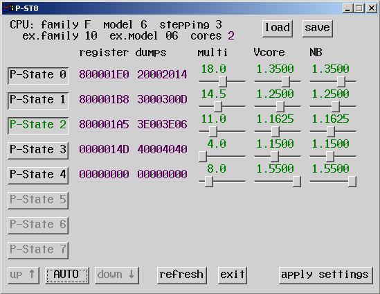
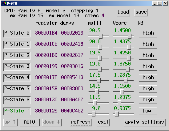
2021 May 12 P-ST8 utility for Win32 on AMD CPUs 10h, 15h
This is the second release of my overclocking / power management utility. It's similar to PhenomMSRTweaker but designed to also support socket FM2 CPUs. It has only been tested on Windows 2000 with Extended Kernel and two different CPUs (Regor-based Athlon II X2 and Richland-based Athlon X4). It allows both manual selection of a p-state, or automatic throttling based on load. Does not work on 64-bit Windows. NO WARRANTY
|
|
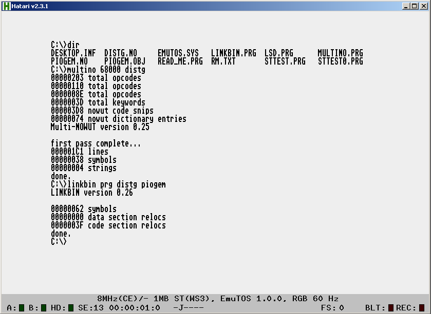
2021 May 6 Atari ST, anyone?
There was a post recently on hackernews about EmuTOS which got me thinking. I had never used an ST before, but given that it is another 68K system, how hard would it be to add it as another target for LINKBIN? I downloaded Hatari, and seeing the SDL2.DLL in there I expected it to have broken keyboard input on Windows 2000. Turns out, it works fine! Then I just needed some info on how to build a .PRG and do some basic GEMDOS stuff. In fact, these are nearly the same as .X and Human68K. Some old GEMDOS docs warned that function $3F for reading data from a file would return junk data in D0 if you tried to read past the end of the file. "Noooooooo! Every other platform returns zero!" But it appears that this behavior may have been corrected in EmuTOS... (hopefully)
|
|
2021 Apr 16 DeHunk 0.97 and UnSuper
Very minor update to the DeHunk 68000 disassembler. Now also includes UnSuper, which is a quick and dirty adaptation of the disassembler to handle SH2 code instead. DeHunk+UnSuper download |
|
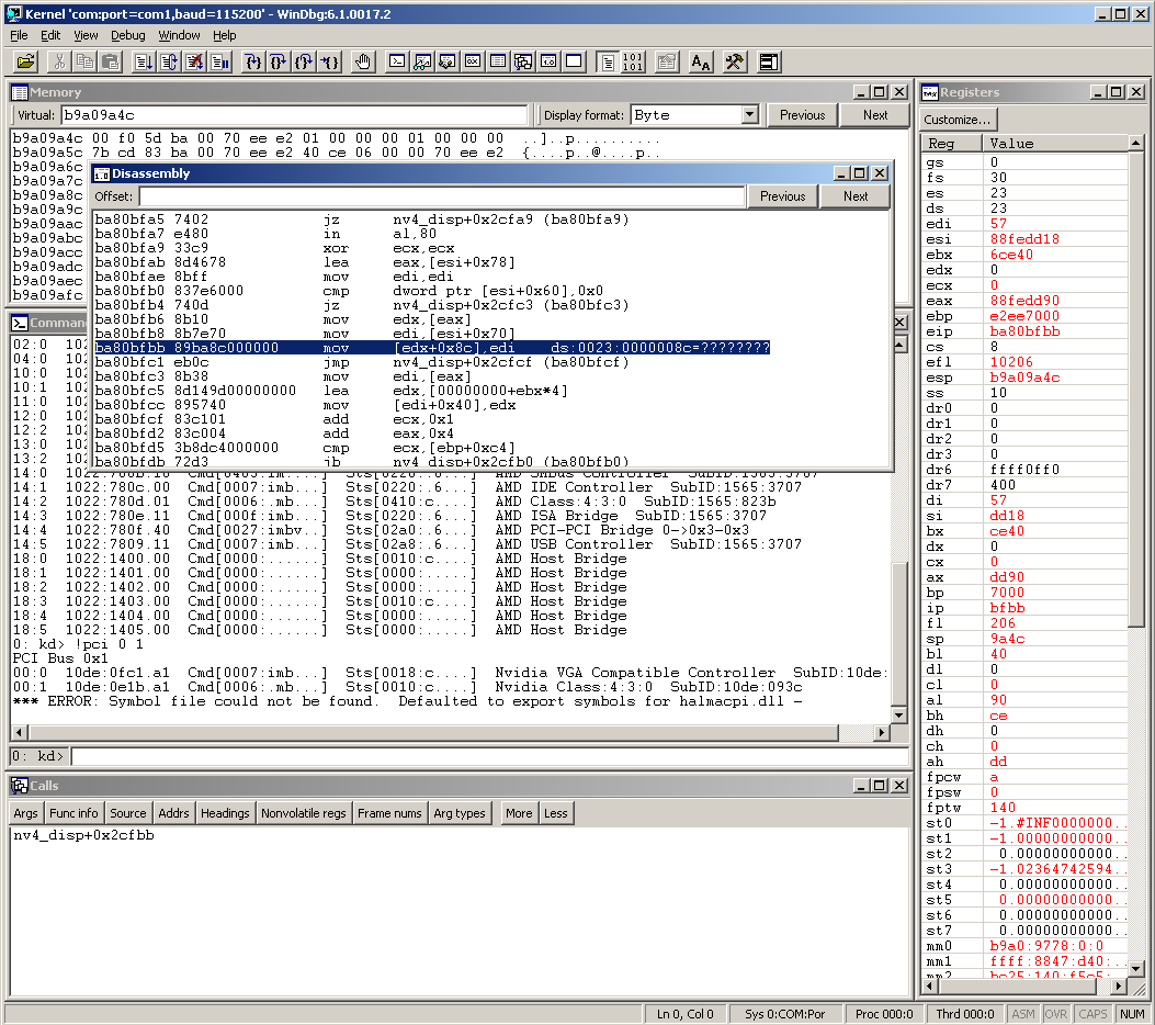
2021 Apr 14 Remote kernel debugging with Windbg
I never had much use for official SDKs, since I don't use any flavor of C programming language. But recently I saw mention in a few different places ( this article for instance ) of using a second system connected via serial cable to diagnose crashes or boot failures. It sounded like something I should try. Maybe I'll even get to the bottom of the video driver crashes on this A88X motherboard? The debugging tools are part of the Microsoft Platform SDK or Windows SDK. If you're lucky you might be able to find the (much smaller) dbg_x86.msi floating around on its own
|
|
2021 Apr 10 Higher-quality Mod player
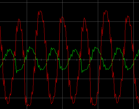
Here is an updated example of a Win32-based Mod player. It contains some minor changes over the 2019 version, and two big changes: First, it eliminates 'pops' in the audio caused by abrupt volume or sample changes, including by looking ahead one row to see which notes will be ending during that time period and can then be quickly faded out before a new note begins. The other big change has to do with aliasing. These are 'phantom' high frequencies that can result from converting from a low sampling rate to a higher one. For instance, a sample in a Mod file playing at C-5 (8287Hz) being mixed into the 44100Hz audio output stream. The simple way to do this conversion is to use an index into the instrument sample that has fraction bits (12 bits in my case) and which increases after each sample by a rate proportional to the note's pitch. (I believe the term for this is Phase Accumulator.) 44100 / 8287 = 5.32 which means each instrument sample is going to repeat in the output 5 or 6 times. The value added to the phase accumulator each time would be the reciprocal of that, shifted left 12 bits for the sake of the fixed-point math: 769. I'll call this the phase increment. Duplicating the same sample in the output those 5-6 times creates an ugly stair-step waveform which is a direct cause of phantom frequencies. In practice, this is what I saw coming out of the 32X:
Seeing how bad it was in visual terms bothered me enough to reconsider doing something about it :) A simple low-pass filter will smooth things out and block some of the aliasing. The more agressive the filtering, the less aliasing that will be heard, however desirable high frequencies are also lost and notes that are low enough are still distorted. Not good. I didn't want to go with linear interpolation because it requires fetching 2 (at least) samples from the instrument data. In the context of a Mod player where you have to be mindful of loop begin- and end-points it seemed like too much of a hassle for something that I would like to run on older CPUs (like a 23MHz SH2). Instead, I came up with something workable that uses adjustable low-pass filters. My earlier attempt at a (fixed) low-pass filter looked like this: Output = ((New - Previous) * X) + Previous If X is one half, then this is the same as averaging each newly calculated value with the last output value. Using a different ratio for X alters the frequency response. What I did is replace X with the phase increment. So for each channel, as long as the phase increment is less than 1.0 (or 4096 after being shifted) then I have Output = (((New - Previous) * PI) shr 12) + Previous |
|
2021 Mar 13 Toadroar revisions and NOWUT version 0.25 release
Running my FPGA CPU design through some more elaborate tests has revealed problems. For instance, instruction fetch waitstates caused instructions to be skipped, a few instructions operated on the wrong data, and no consideration was given to where bytes would be presented on the bus when accessing odd addresses. So I've been busy redesigning it while also tweaking the instruction set to suit the implementation details. I have plans to add interrupts and an instruction cache later. NOWUT 0.25 is here, with bug fixes in the x86 assembler and elsewhere, and two new IF statements. Check the documentation. Download the complete archive. And be sure to get Go Link from Go Tools website. |
|
2021 Feb 20 QMTECH again
Got all three colors hooked up. Added a Toadroar CPU into the mix which can execute code from internal FPGA memory and write to SDRAM. I also have an assembler adapted from an old MultiNO and a utility to convert to text-based (argh!) MIF (memory initialization file) format used by Quartus. Using the MIF means I can reload the FPGA with updated code without having to go through the entire compilation process in Quartus (which takes the better part of a minute otherwise). Then I used a PLL to pump up the clock speed to 80MHz. When I did that, the inverted clock being sent to the SDRAM (as seen in my last project upload) became inadequate, and the first out of every eight pixels was showing garbage data on the screen. Setting up a separate PLL output to create another 80MHz clock at 90 degrees out-of-phase fixed this.
|
|
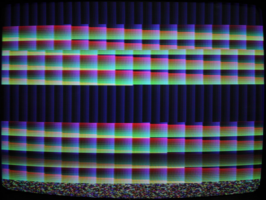
2021 Feb 13 more experiments on QMTECH Cyclone IV Core Board
I revised my CRT controller, made a basic SDRAM controller with the help of the W9825G6KH datasheet, and then connected them together in an outer module. Now I can view uninitialized garbage data from the SDRAM on the screen, press a button to draw some black stripes in it, or press the other button to scroll down. The garbage data at power-on is itself a bit curious. There are tightly repeating patterns, and after scrolling down for a while (256K words I think it is...) the pattern changes completely. future plans: This is the complete Quartus project. |
|
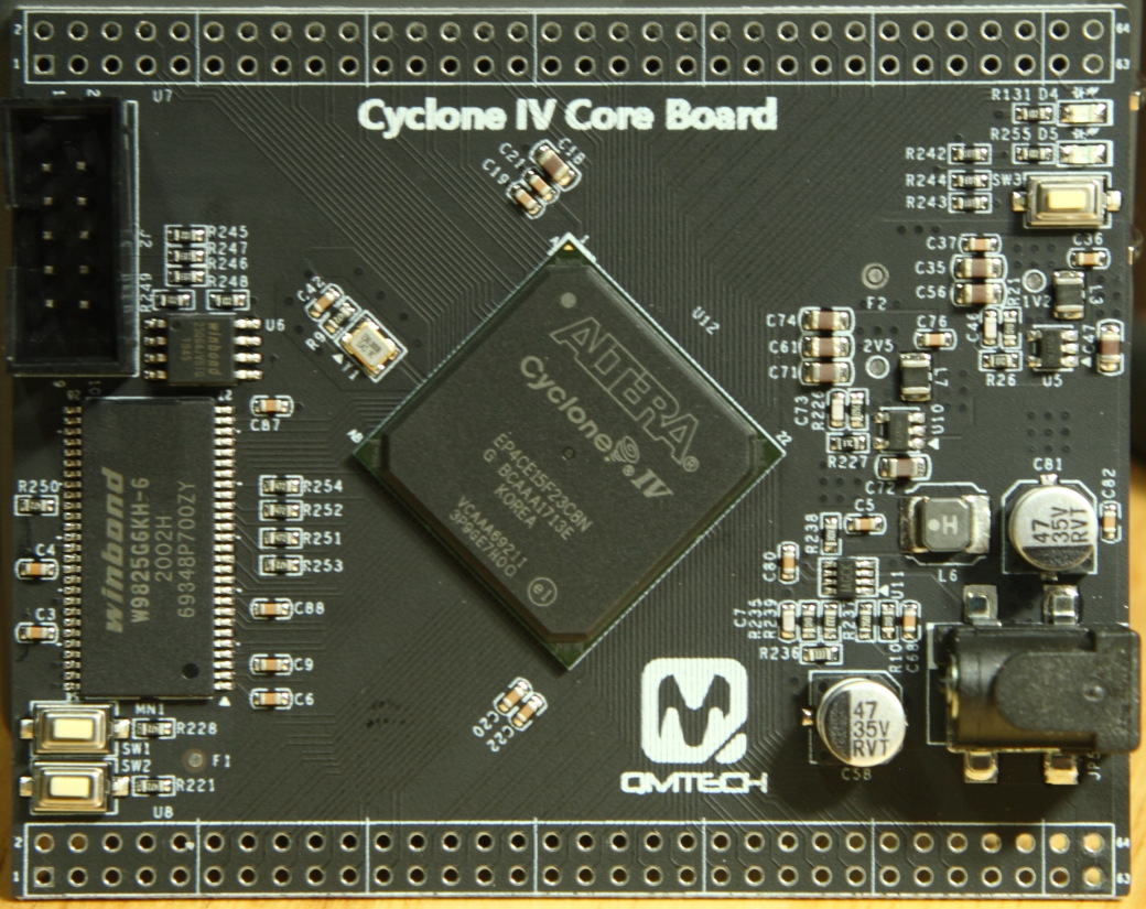
2021 Feb 4 another FPGA toy
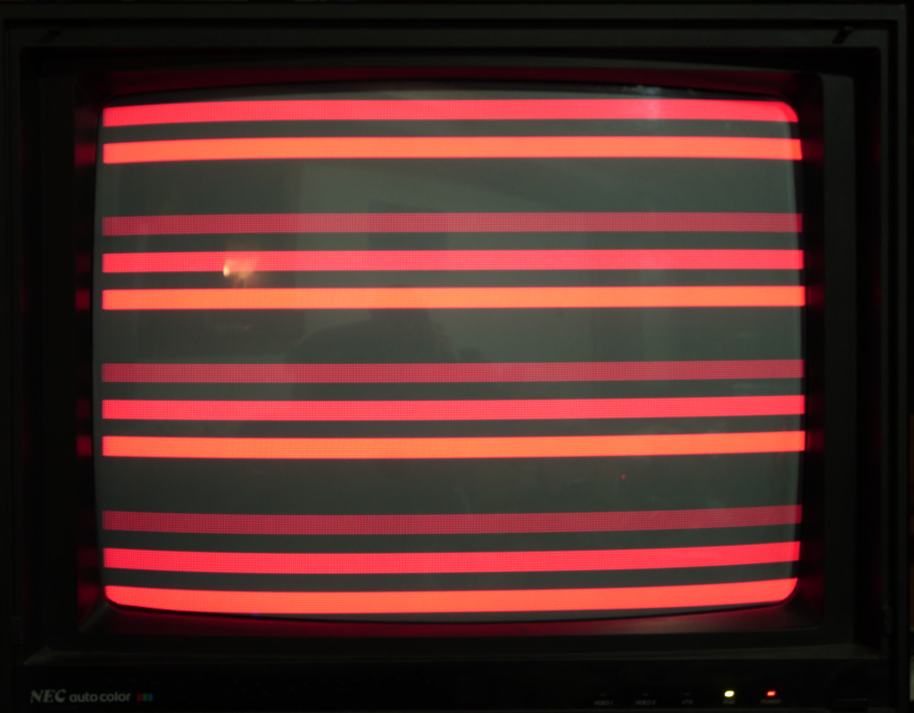
This is a nice bang-for-the-buck Cyclone IV project board featuring 15K LEs. Sadly, it is devoid of connectors other than the rows of unpopulated solder pads, and includes only one LED and two buttons for general purpose use. However, it does boast 32MB of SDRAM ! Having already experimented with the CPU, serial, and audio cores on the Storm_I board, video was the next thing on my agenda. I decided to start out with some 15KHz RGB, using my NEC CM-1991a monitor. My reasoning was that any VGA monitor since the mid '90s is likely to show a blank screen or an error message if the incoming signal is in any way defective, whereas I know the old NEC CRT will show something on the screen even if it is all garbage. Plus, it is already there sitting just a few feet away, with a dodgy custom RGB cable hanging out of it that I used to test an Amiga Firecracker 24 board. I read on another page the idea of using a 270 ohm resistor between the 3.3V FPGA output and the video input, to get something approximating the right voltage (assuming 75 ohm load in the monitor). I didn't have a 270 so I used a 330. Viewing the output signal (red, that is) with a scope showed a ~.5V DC offset (with ~1V peak) and I have to say I don't know why that was there but turning down the brightness on the monitor effectively removed it. I used 100 ohm resistors on the h-sync and v-sync.
I divided 50MHz by ten, yielding roughly 240 pixels horizontally, and created a couple of extra intensity levels by switching the output off early during one pixel. Oddly, the camera saw the red bars as orange. I even mucked with the white balance and tint in DPP before saving the JPEG in an attempt to make it more red, which is certainly how it looked to the naked eye. But the brightest red bar still looks orange. *shrugs* This is the verilog code. |