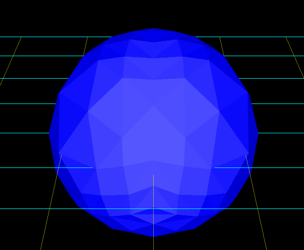
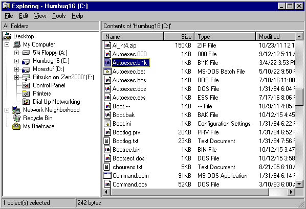
Using an 8-sided 'diamond' as a starting point instead of a tetrahedron is easier to calculate and yields a nicer shape. At 32 faces it already looks vaguely spherical, and is quite good with 128.

|
2026 Jun 13 Spheres part 2
Using an 8-sided 'diamond' as a starting point instead of a tetrahedron is easier to calculate and yields a nicer shape. At 32 faces it already looks vaguely spherical, and is quite good with 128.
|
|
2026 May 27 NOWUT version 0.36 release
This release slightly improves 68000 code generation and has a number of bug fixes, notably the SWAP statement, which allows two operands of different sizes but previously did not handle this correctly. Check the documentation. Download the complete archive. And be sure to obtain Go Link from Go Tools website. |
|
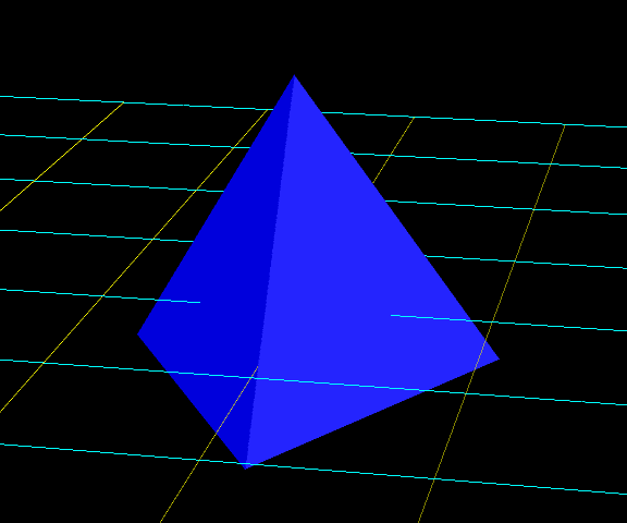
2026 Mar 24 Easiest way to make a sphere out of triangles?
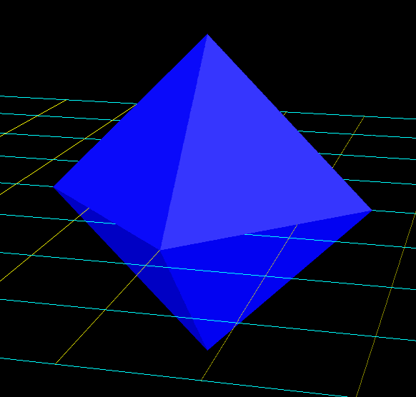
I tested an idea to algorithmically make a sphere mesh by starting with a tetrahedron and then subdividing each triangle into four triangles. The position of each new vertex begins as the halfway point along an edge, and then is adjusted to match the sphere radius. Every iteration of subdividing triangles quadruples the number of triangles. The edge length of the largest regular tetrahedron that fits in a sphere is calculated by dividing the sphere diameter by the square root of 1.5 It works but unfortunately it doesn't look much like a sphere until you get to 256 triangles.
|
|
2026 Mar 15 Proper reverse engineering of 1802-based Motronic - Part II
I've now analyzed all of the code from the 027 ROM, though the meaning of all values is not yet understood. It seems likely that the scale of the values in the ignition map is equal to the angular size of a flywheel ringgear tooth divided by 4. 360/137/4=0.657 degrees for the M20, and 360/116/4=0.776 degrees for the M30. It's also stated on this archived site. This scale is used internally for calculating the advance. The value from the ignition advance table is adjusted by some other factors, like a coolant temperature based advance table, and an intake air temperature based retard table. However, the final value is shifted right by one bit, which means the actual precision of the ignition system is only half as good: 1.314 degrees for the M20, and 1.552 degrees for the M30. The big news of the day is that having finished with the 027 code, I started comparing the 007 and 008 code. Pretty soon I found that the 008 dump is flawed, as the third chip (address $800~$BFF) has bit 1 stuck high. When I dumped the chips in 2024, I noticed that the first chip had bit 1 stuck high, but failed to notice the third one having the same problem. So I'll need to try dumping it again before I can extract accurate parameters A preliminary interpretation of the 027 ignition map would look like this (below). It's not much, and would explain why I was easily able to get both better power and better mileage with Megasquirt on an M20 with 885 head. ETA (027): 480 15.111 22.995 22.338 21.024 20.367 19.053 18.396 17.082 14.454 15.111 13.140 5.256 3.285 1.314 1.314 1.314 640 12.483 16.425 16.425 20.367 21.681 21.681 21.681 19.710 17.739 16.425 13.140 9.198 5.256 1.971 1.314 1.971 800 1.314 8.541 8.541 15.768 22.338 23.652 21.681 19.710 17.739 16.425 14.454 9.855 5.256 3.942 3.285 3.285 960 2.628 8.541 8.541 15.768 22.338 25.623 23.652 21.681 18.396 16.425 15.768 11.826 6.570 4.599 4.599 3.942 1280 4.599 11.169 17.739 25.623 27.594 25.623 23.652 21.681 21.024 21.024 19.053 15.111 11.169 8.541 8.541 6.570 1600 9.198 19.053 24.966 30.879 28.908 28.251 26.937 26.280 26.280 24.966 22.338 19.053 15.111 13.140 13.140 11.169 1760 15.111 21.024 35.478 34.164 30.879 28.908 26.937 26.280 26.280 24.966 24.309 20.367 17.082 14.454 13.140 11.826 2240 19.710 33.507 32.850 31.536 31.536 31.536 30.879 30.879 30.879 29.565 26.280 23.652 19.710 16.425 15.768 16.425 2720 21.681 30.879 25.623 24.966 24.966 24.966 24.966 23.652 23.652 23.652 23.652 22.338 20.367 17.082 15.768 17.739 3040 26.280 24.966 24.966 24.966 24.309 24.309 22.995 21.024 20.367 20.367 20.367 19.053 15.768 13.797 11.826 15.768 3360 26.280 22.995 22.995 22.338 22.338 20.367 20.367 20.367 19.053 19.053 18.396 15.111 13.797 11.169 9.198 11.826 3680 26.280 26.280 26.280 24.309 24.309 23.652 22.995 22.995 22.995 22.995 22.995 21.681 17.739 13.797 11.826 13.797 4160 30.222 30.222 30.222 28.908 26.937 26.937 26.937 26.937 26.937 26.280 26.280 21.681 19.710 17.082 11.826 14.454 4320 36.135 36.135 34.164 32.850 32.193 30.879 30.222 30.222 28.251 26.937 26.280 22.338 20.367 17.082 13.797 14.454 4800 38.763 38.763 38.763 37.449 36.792 35.478 34.821 32.850 31.536 31.536 31.536 30.879 26.280 24.309 19.710 17.739 4960 38.763 38.763 38.763 37.449 36.792 35.478 34.821 32.850 31.536 31.536 31.536 30.879 27.594 25.623 21.681 15.768 |
|
2026 Mar 7 A brief history of the dying WWW
1995: JavaShit announced. Early 2000s: ISPs colluded to create the Apartheid Internet. They advertised and sold "unlimited" internet service which was very much limited, thereby creating a new (under-)class of crippled, 'consumer grade' internet connections. The effects of this can't be overstated. Many of the most popular sites in the present day have free hosting as their main attraction. Post images on photobucket because you can't host them yourself. Post source code on github because you can't host it yourself. Post video on pootube because you can't host it yourself. And so on. Most of these sites or 'platforms' would not even exist if not for the Apartheid Internet. 2012~2014: The HTTPS distraction is rolled out. One purpose of this is to redefine what 'security' is. A man-in-the-middle attack which injects malicious JavaShit is a security hole, because JavaShit is a security hole. It's remote code execution, often unwanted by the user and not even requested. The user can request example.com/photo.jpg and instead of receiving a file, or an error, get a pile of JavaShit which is automatically executed by modern browsers. That's outright fraud. But with HTTPS, we pretend that only the injection is the security hole, and that remote code execution itself is perfectly fine, as long as it's not from a man-in-the-middle. A side effect of HTTPS was that every old browser was now blocked by some web servers. As usual, browsers which remained unchanged were deemed to be the problem, even though it was the web servers that had changed, in a form of deliberate sabotage. According to the software industry belief system, if you rip up railroad and replace it with canal, it's the fault of the trains for not being able to float. Now that browser choice had been destroyed, an advertising and spyware company called google was practically handed a monopoly. This resulted in an ongoing downward spiral of bloated, abusive, and incompatible websites, and even webcrap that bundles a browser being passed off as native software. Late 2010s: Craptchas and 2FA scams proliferate. Now that website operators have ordained themselves with the right to run arbitrary code on the user's system, what can't they do? Could they coerce the user into repeatedly solving defective puzzles without compensation for their labor? Could they coerce the user into buying a surveillance phone, paying a subscription, and keeping it nearby and turned on while they use their computer? Could they pretend that both of these things are for 'security' and not just blocking legitimate logins from users who already entered a correct username and password? 2020s: Allegations of a bot apocalypse are made. Suddenly, website operators are claiming that their (often extremely bloated) pages are costing them too much in bandwidth. Since the highly advanced technology known as "rate limiting" has apparently been lost and forgotten, the only solution they can find is to block lots of users. Which users should they block? The "bots" of course. What is a bot? Who knows! But apparently "bots" are easy to identify, either by user-agent strings or by sending some unwanted JavaShit malware. They say that humans can execute JavaShit malware, whereas "bots" cannot. Clearly a solid plan. And when "bots" are 'detected', we'll display an error page informing the user that he/she is a "bot". That will help. Somehow. In the near future: "Age verification" is used as a trojan horse. The most obvious consequence of "age verification" mandates being made by corrupt governments is that all online activity ends up being associated with a digital ID. But another possibility has now been revealed. Under the guise of relieving individual vendors/providers of the burden of validating a digital ID, it could instead be implemented at the OS level. So the worst Big Tech corps would now be in charge of granting adult privileges to anyone who wanted to do anything online (or off!). Needless to say, this means they can abstain from granting privileges if the user does anything naughty, like use unfashionable software or hardware. How much longer until the WWW is completely dead? On a tangential note: editing wikipedia is not generally worth the time, for various reasons, and it's been a long time since I tried to do it. Even in the past, I didn't bother editing the articles, instead I would edit the talk page to point out that something was wrong in the article. Now I can't even do that. I can pretend edit, but saving changes is locked behind some craptcha garbage that doesn't work (or even appear). |
|
2026 Feb 24 Proper reverse engineering of 1802-based Motronic
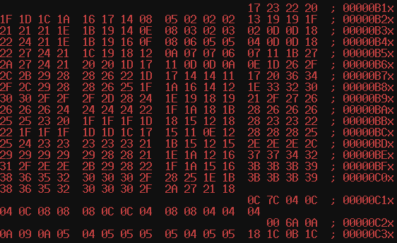
Over on my Motronic page I have some information which is mostly solid but very incomplete. This work is from 2006 ~ 2010, and some of it was based on internet legends or faulty experiments. Now that I've acquired another M20 engine, it's a good time to figure out this thing for real. I have ROM dumps from an 007 ECU ('82 528e), 027 ECU ('85 528e), and after solving the puzzle of how to dump CDP 1833 chips, an 008 ECU ('83 633CSi). The 007 and 027 ECUs are for the same engine, and are essentially interchangeable. The ROMs are not the same though. I suspect one reason for this is that in '84, cars were equipped with a barometric pressure switch to help maintain emission standards at high altitudes. The 008 ECU on the other hand, is for a different engine, and has other differences in its ROM. I've analyzed about half of the code so far, and several dots are beginning to connect.
According to legend, there is supposed to be an ignition map and fuel map in here. Disassembly of the code at $14F reveals how things are really organized. The routine is called multiple times, doing somewhat different jobs depending on how various registers were setup beforehand. The first time it's called, it compares the current engine speed with the values at $C1C and $C1D. $7C is the last row of the table, 4960RPM. $0C is the first row, 480RPM. For values that are in between, it works backward from the end by adding from the string of digits at $C1E. Each of these numbers corresponds to the RPM difference between rows, yielding these values for the RPM axis of the table: 480, 640, 800, 960, 1280, 1600, 1760, 2240, 2720, 3040, 3360, 3680, 4160, 4320, 4800, 4960 That's 16 rows. Turns out the entire table is for ignition timing. In the process of calculating the table position, it also records a 2-bit fraction, presumably for interpolating between values. Finally, it jumps into a code block of repeated ADD instructions, effectively multiplying the result by $10 (the row width). The next call to the routine handles the other axis, airflow / load, in a similar fashion, using the values beginning at $C2D. This one doesn't get multiplied at the end, instead two bits are tested from memory-mapped I/O port $2003, and the result can be forced to 0 or $0F. Presumably these are the throttle switches. Idle spark advance must come from the first column, and WOT spark advance from the last column. As for the values within the table, it seems unlikely that they are in units of 1 degree. That'll have to be measured on a running engine with a test ROM. One other observation concerns the apparent RPM scale factor at $88B. On the M20 engine, it's $B3. In the 008 ECU, for the M30, it's $D6. If I multiply these by the respective numbers of flywheel ring gear teeth (which are read by a VR sensor), the results are very close. The M20 flywheel supposedly has 137 teeth, though I haven't counted. 137 * 179 = 24523. The M30 has 116. 116 * 214 = 24824. |
|
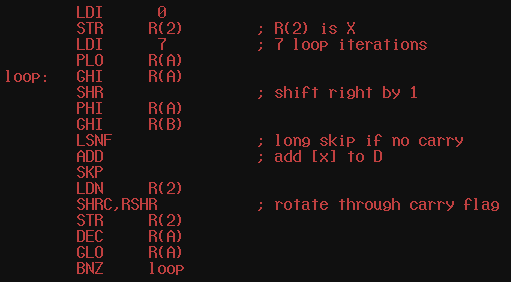
2026 Feb 16 Deciphering RCA 1802 code
The 1802 instruction set is a bit unusual, adding another layer of fog to the task of reverse engineering stuff. This routine has a loop, it has shifts, and it has addition. Pretty soon it started to look like multiplication. On the other hand, why only seven iterations?, and why does the result of the add get right-shifted into the abyss? AFAICT, it takes R(B)-HI, bits 0~7 of R(A)-HI, multiplies them, but only keeps bits 7~14 of the result.
|
|
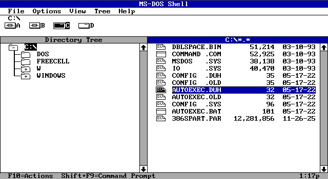
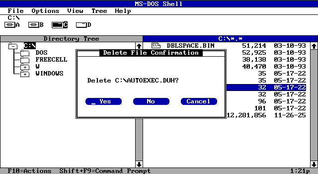
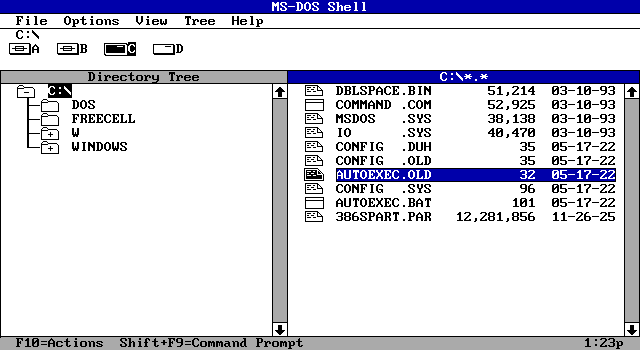
2026 Feb 3 a thing that broke thirty years ago
I saw a thread about file managers, and started thinking back to DOSSHELL, which is maybe the last file manager I found useful. DOSSHELL stopped being useful because it doesn't like partitions with more than 65535 files. (Long file names are also a bit of a nuisance, as always.) But it was usable via keyboard in a way that subsequent file managers from MS no longer are. In DOSSHELL, you can highlight a file. Then you can press the 'delete' key. After the file is deleted, a different file becomes highlighted. Amazing, right?
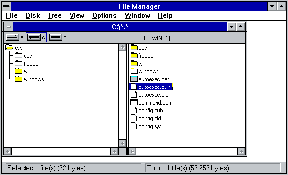
Windows 3.1 is similar, though with an additional (redundant) confirmation step.
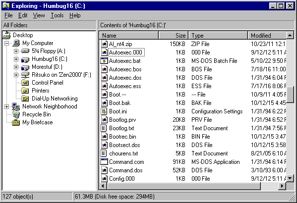
In Windows 95 something went horribly wrong, as you'll soon see. We can highlight a file. We can delete a file. But what happens after that?
Autoexec.000 has a dotted line around it, but it's not really highlighted. What do you think will happen if you press 'delete' again? Nothing will happen. Instead of selecting the next file, we've entered a state of limbo where nothing is selected. This UI is broken. And it's like this all the way up to Windows 7. (After that is when MS started shipping cell phone OSs. I don't know if those still have file managers.) |
|
2026 Jan 27 An improved VGMSTRIP
This one not only shrinks VGM files by removing PCM data, it also consolidates wait commands and preserves loop points. |
|
2026 Jan 25 extending MBFAST
I started this FreeBASIC program all the way back in 2014, to make simple models for use on a 3D printer. I added a few unrelated features just for the fun of it. But now I expect I will need 3D assets if I ever want to make a game based on my 3D engine. That will mean not just meshes, but material properties, texture coordinates, animation related stuff, and various other flags. A lot of stuff needs to be retrofitted to the program. It would also be good to support popular file formats used for these things, though it seems these file formats are largely 1) undocumented, or 2) terrible (ie. text based). I held my nose and managed to load a Wavefront Obj. So that's something. 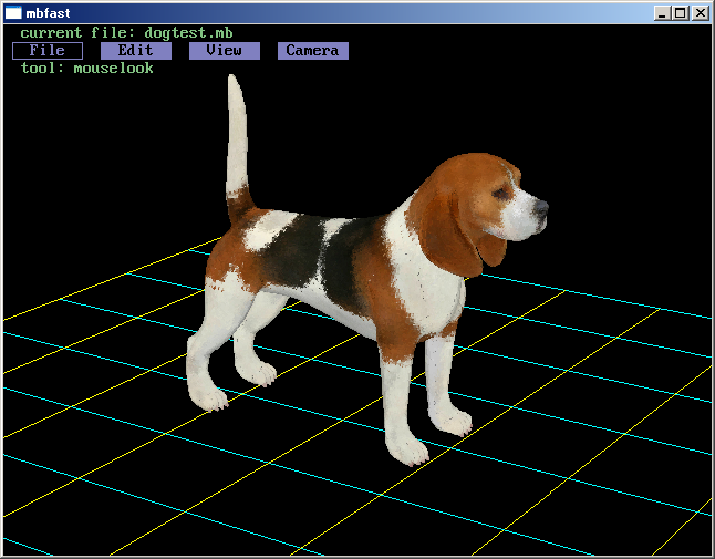
|
|
2026 Jan 12 MIDI to VGM translator, beta 5
Update to this program: |
|
2026 Jan 10 even more NOWUT bugs
The new 'appgetpath' routine in the latest PIODOS.NO, contained some long conditional jumps which should have been short jumps. It still works fine on 386 and above, but crashes on 286 or below because long conditional jumps don't exist on 286 or below. This is another item which will need to be fixed in the next release. |
|
2026 Jan 9 yet more bugs
A few programs I posted in source form (eg. vgz2vgm, vgmtos98, s98tovgm) have a bugged variant of the routine 'readcmdstr' which can return garbage data if it is called more times than there are command line arguments. This part: should have been this instead:

|
|
2025 Dec 24 NOWUT bugs
I discovered a rarely occurring bug when compiling for SuperH. A datadump that exists during the first pass can be eliminated during the second pass, caused by long jumps getting optimized to short jumps, and as a side effect the counter for datadumps does not advance and the list of datadumps from the first pass is no longer tracked correctly. A subsequent datadump may then overflow. This will need to be fixed in the next release. |
|
2025 Dec 12 ADPCM encoder bugs
Turns out the program I posted on May 30th is buggy, mainly in calculating the sample length, but also the encoding algorithm. I attempted to correct it with this:
;        oldsampl=y*z.sd shr 2.sb+_
        oldsampl=y shl 1+1*z sar 3+_
Oddly enough, it doesn't sound much different. I'm not convinced this is correct either. |
|
2025 Nov 26 NOWUT version 0.35 release
This release has several minor fixes and improvements. 8086 code is now faster due to a change in how shifts are done. NOWUT86 compiling itself is nearly 10% faster. The main addition is a set of new routines in the PIOxxx modules. 'memrequest' and 'memreturn' allow programs to allocate and free memory blocks at runtime. 'appgetpath' allows a program to locate files in the same directory as its executable, regardless of the current directory. These routines may become useful in future releases of eg. the disassemblers. (In PIOGEM and PIOLNX, appgetpath only returns a null string. I can't find a reliable way to obtain this information in EmuTOS, and the *nix people are ideologically opposed to it.) Check the documentation. Download the complete archive. And be sure to obtain Go Link from Go Tools website. |
|
2025 Nov 16 updated text/hex editor: RaeN 0.92
changelog:
download RaeN 0.92 here (win32 only) (see the Oct 2022 posting for the Shift-JIS font and additional info) |
|
2025 Nov 9 Megasquirt post-mortem (Part Two)
Megasquirt, at least in its original configuration, has two outputs to control fuel injectors. When there are more injectors than this, they'll be separated into two batches, with the injectors in each batch being connected in parallel. (In my case there are a total of six injectors.) The software can be configured to turn on both injector batches at the same time, or alternate from one to the other. On a four-stroke engine, each injector has to operate at least once per two engine rotations, though operating more than once is also possible. There are pros and cons to each option, for instance: Since a single 1MHz timer is used to control both batches, a bit of juggling needs to happen in 'alternating' mode when the pulsewidths overlap. The original code had a minor bug where a 16-bit subtraction didn't account for the borrow, which could throw off the timing by 256 microseconds. In the situation where pulsewidths are long enough to overlap, 256uS is unlikely to be a significant error. Nevertheless, I have fixed the bug, which took more code than one might expect because the timer registers require reading the high byte first for some reason. Considering all of that, I was leaning toward using '2 squirts alternating' but my new acceleration algorithm doesn't operate optimally in alternating mode. I would have needed to find some more free memory locations to keep track of two offsets at the same time. Instead, I continued to run with '2 squirts simultaneous'. Latest source and Megatune files for TJ's mod, version M30-3e |
|
2025 Oct 26 Megasquirt post-mortem (Part One)
A decade ago, I posted my slightly modified version (known as M30-3d) of MS1 Extra firmware, which is the 68HC908 assembly code powering the (original, 8-bit) Megasquirt fuel injection controller. I used it thereafter to run a BMW M30B32. Last year the MS went dead suddenly and I had to pull it out to diagnose and repair. I decided to revisit the firmware code while I was at it. The main modification that I had made was a new acceleration algorithm (which I called NMA) to replace the official one. The reason I did this was because the official one relies on a throttle position sensor. My engine didn't have a TPS, and I didn't want to add one. What is an 'acceleration' algorithm? It's all about how the fuel injection responds to changes in engine load. As long the engine speed, load, and temperature remain the same, the amount of fuel injected (as determined by the opening duration of electronic fuel injectors) can also remain the same. (There are some additional variables which play a lesser role, like fuel quality and atmospheric conditions.) When engine load is changing, there are yet more confounding factors. How much latency is there between measuring the change in load and the next injection cycle? How much fuel remains in the intake port in between intake cycles? How much fuel that was condensed in the intake port at a higher manifold pressure will vaporize when the manifold pressure goes down, or vice versa? My NMA code was intended to temporarily inject additional fuel whenever manifold pressure (MAP) increased, or inject less when MAP decreased. This is similar to what the official TPS accel does. But it turns out there were problems with my implementation.
I believe I've corrected these problems, at least for the case when both injector banks are activated simultaneously. The algorithm could be further improved when using alternating injector banks, but I'll address that more in the next post. |
|
2025 Jul 26 upgrading the hardware and keeping the software
Reinstalling Windows has long been a popular "solution" to various problems (real or perceived), even though it's an utterly terrible thing which should be avoided at all costs. I am happy to go a decade or more without reinstalling if I can help it. Why? Because a new install requires one to fix all of the crummy default settings, reinstall all of the drivers and codecs, and deal with various applications which will quit working because their crap went missing from the registry. (And that's assuming that you didn't 'reformat' and thereby delete all the applications, another popular but strange practice.) But sometimes when you try to boot an existing Windows install on a new motherboard, it's FUBAR. You can monkey around all day with windbg and regedit and maybe after that it's still FUBAR and you have to admit defeat. What then? Running Windows 2000 on my new motherboard requires new ACPI and AHCI drivers from Windows XP Integral Edition, plus a hacked HAL, and NTOSKRNL extender. I set it up in a separate case to experiment with it until I could get a working install, so I could continue to use my main machine with the old motherboard. (Aside: AHCI has been a giant boondoggle, resulting in uncountable wasted man-hours worldwide due to its incompatibility with PCI IDE. It had a negligible performance impact and is now rendered moot by SSDs.) Could I get my old Windows 2000 install to boot on the new motherboard by inserting the new drivers? Unlikely. In fact, I tried to make it boot by inserting the driver for a JRAID PCIe SATA/IDE card and failed at that. So I didn't attempt doing it with AHCI. Instead, when the time came I just renamed WINNT to WINNTold, and copied the WINNT directory from the new install. Keeping the DOCUME~1 directory around maintains the NTUSER.DAT registry hive and some application data, which solves many of the issues with a new install. Drivers still need to be reloaded, but keeping around the old WINNT directory can be useful for the sake of digging out OEMx.INF files and whatnot. I also exported the old SOFTWARE hive to a text file so I could extract various parts with NOTEPAD and import them again into the new registry. This was crucial for keeping the font settings I had setup for running Japanese games. Some applications still had problems, and it was difficult to know which registry entries, if any, were the cause. For instance, Canon DPP now failed silently when I tried to launch it. Going through a trace with Ollydbg, I found a failed call to CoCreateInstance. So yes, the problem was with the registry. But rather than try to hunt down the right ones, I just installed a dummy copy of DPP by running DPP100-E.EXE, and now stuff works again. (The installer for DPP 3.14.15 refuses to run on Windows 2000, even though the application itself works.) 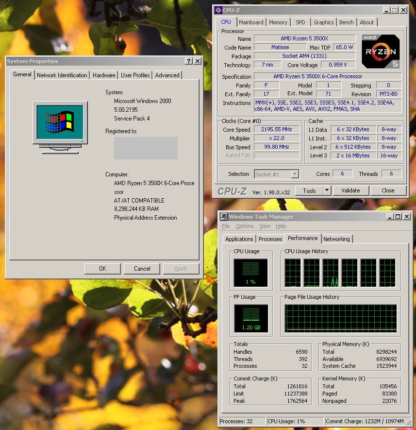
Windows 2000 is now ready to go. But I have a dual boot with Windows 7. The old PC had two HDDs, but I've replaced one of them with an SSD and rearranged the partitions. Windows 7 was not booting anymore. Unlike Windows 2000 which contains boot settings in a plain text file, BOOT.INI, Windows NT 6 and later moved the settings to a binary blob called BCD. BCD is like a registry hive, and can be edited, but there is little progress to be made by editing it because the configuration is also obfuscated by GUID nonsense. The only way I know to fix this thing is by booting a Windows 7 DVD and requesting it to do a repair. So I did that. Except the DVD I have is "Home Premium" whereas the OS installed was "Professional" and so it declined to do the job. BUT! After I copied over a dummy install of "Home Premium" to the same HDD, then the DVD went ahead and fixed the BCD so it could boot both "Home Premium" or "Professional". (Though I only need one, and the "Home Premium" is already being used on another machine.) Well, not quite. Windows 7 could begin to boot, but still didn't know to load AHCI drivers, since the old motherboard was in IDE mode. Thankfully this isn't too hard to fix in Windows 7. After booting from the DVD, you can press Shift+F10 to get a command prompt. Run regedit. Use 'load hive' to access the Windows 7 SYSTEM hive. Find Services\MSAHCI, and set 'Start' to '0' |
|
2025 Jun 6 Snooper SSD benchmark
I happened to run Snooper with a SATA SSD connected and got a result far beyond any HDD or compactflash card. 
By contrast, I think the video benchmark topped out somewhere around this level back in the socket 7 era. The CPU benchmark is a small loop of 16-bit code, so it isn't terribly relevant on modern CPUs (this one being a Zen 2), but here are some historical results for comparison: 8088 at 4.77MHz = 2.1 8086 at 7.16MHz = 4.3 286 at 6MHz (IBM AT) = 6.7 386DX at 25MHz = 45 486 at 100MHz = 274 |
|
2025 Jun 1 partition realignment with a sector editor
I connected a new SSD and created a partition with Windows 2000. The entry in the MBR (beginning at $1BE) initially looked like this: 00 01 01 00 0C FE FF FF 3F 00 00 00 DB F8 CE 1DThis is the traditional (non)alignment where things begin at sector 63. Bytes 1,2,3 indicate head 1 (the second head, since the first is 0), sector 1 (the first sector, since 0 is not a valid sector number), and cylinder 0. Bytes 8~11 contain a dword representation of the sector number, which agrees with the CHS address. The newer custom for flash-based storage media is to align on a 1MB boundary. That means sector 2048, rather than 63. My modified partition entry is this: 00 20 21 00 0C FE FF FF 00 08 00 00 DB F8 CE 1D The final dword is the size of the partition. You might expect that it will need to be decreased when the beginning of the partition is moved ahead. But in this case, Windows had left a few MB of unused space at the end of the 'disk' anyway, so I left the size as it was. After that I ran FAT32FORMAT on it. Later, if I try to make it bootable, I might have to revisit the MBR to flag the partition as bootable. |
|
2025 May 30 ADPCM encoder (MSM6258)
Here is a Win32 program to convert an uncompressed, mono .WAV file to ADPCM, and another program to play back the resulting sample on X68000. With NOWUT source. download here |
|
2025 May 3 new release of P-ST8 utility (with Zen support)
This Windows program for CPU performance control has been extended to support early Ryzen CPUs. In theory, it now supports desktop CPUs ranging from Phenom to Zen 3, though only a small subset of these processors have actually been tested. Note that voltage readings are still incorrect on Ryzen. download here |
|
2025 Mar 24 vgmstrip
This is a quick and dirty program to filter a .VGM file so that it contains only YM2151, YM2203, YM2608, YM2612, or SN76489 data. That means files that also contained PCM data will shrink, which can be useful when playing them with OPNZ which runs from conventional memory and doesn't play PCM anyway. vgmstrip - DOS EXE and source |
|
2025 Mar 2 NOWUT utility to fix the checksum in a (32-bit) PE file
Generally the checksum is ignored, but in the case of Windows drivers and certain other system files it does matter. Drivers with a wrong checksum will be rejected by Windows while booting. This utility runs in DOS, which is handy because under DOS you can modify files that would otherwise be locked while Windows is running. PECHK - DOS EXE and source |
|
2025 Feb 28 6x disassemblers
This is a new release of NOWUT-based disassemblers. A disassembler for Z80/Z280, 1eighty, has been added. The x86 disassembler, PEon, has been updated with fixes and new capabilities. There's a nuisance that is particular to x86 and Z80 code, and that is misaligned disassembly. It doesn't happen on architectures that use fixed-length instructions, and is possible but much less frequent on 68000 where instructions are at least 16 bits and aligned on a word boundary. When there is data mixed in with code, it's hard to know where the data ends and code begins on x86 or Z80. Any single byte value could be the beginning of a valid instruction. There are multibyte values which don't result in a valid instruction, but generally not enough of them to distinguish between code and eg. an ASCII string. Strings mostly disassemble to LD instructions on the Z80. On x86, a variety of things will come out, like ARPL, conditional branches, INC and DEC, prefixes, etc. The worst thing is when the beginning of a routine gets mangled. For instance, a $00 byte before a PUSH EBP instruction causes it to be disassembled instead as ADD [EBP-$75],DL. PEon has several new checks designed to avoid this problem. The letter 'E' is very common in English text, but the byte $65 (a GS segment override) is very uncommon in real code. Not only that, but a $65 before an INC/DEC register instruction or a conditional branch serves no purpose, so it becomes safe enough to disqualify $65 $43 or $65 $74 as being legitimate code. Win32 builds, i386 Linux builds, and source: 6x disassemblers |
|
2025 Feb 25 Cloudflare = fartcloud
Cloudflare is in a race with Google to see who can ruin the web more quickly. More websites are now inaccessible behind a fartcloud wall, or unusable due to including unwanted fartcloud malware that does nothing useful while BLATANTLY LYING about "checking the security" or some such. Who came up with that idea? Was having their javascript garbage display a message that said "cleansing your aura" or "renewing your spirit energy" thought to be unsatisfactory? Or was it commanded from above that the magic word "security" must be included, because anything that happens on a computer is guaranteed to be legitimate when it contains the magic word? As long as they're committed to lying, why not say "checking the security of your neighborhood" instead? Web users would be so pleased to know that their neighborhood was secure. Or you could make it more inclusive: "checking the security of your community." Wow! I love javascript now! It's securing my community! Please, fartcloud, inject some more of your javascript! |
|
2025 Jan 28 a few more wrong x86 opcodes
The 80x87 instructions FSTCW, FNSTCW, and FSTP (80-bit version only) assemble and disassemble incorrectly in the current versions of NOWUT and PEon. PEon also fails to disassemble some MOVs to/from control and debug registers. It will do so only when the 'mod' field is 0, while documentation suggests that the mod field is actually ignored for these instructions and can be any value. |